
Automatic rotary transfer apparatus and method

Active Publication Date: 2014-08-28
GRAHAM PACKAGING CO LP
View PDF6 Cites 12 Cited by
  • Summary
  • Abstract
  • Description
  • Claims
  • Application Information

AI Technical Summary

Benefits of technology

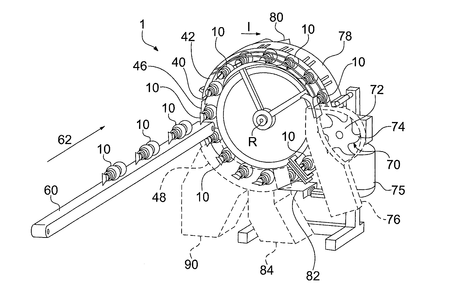
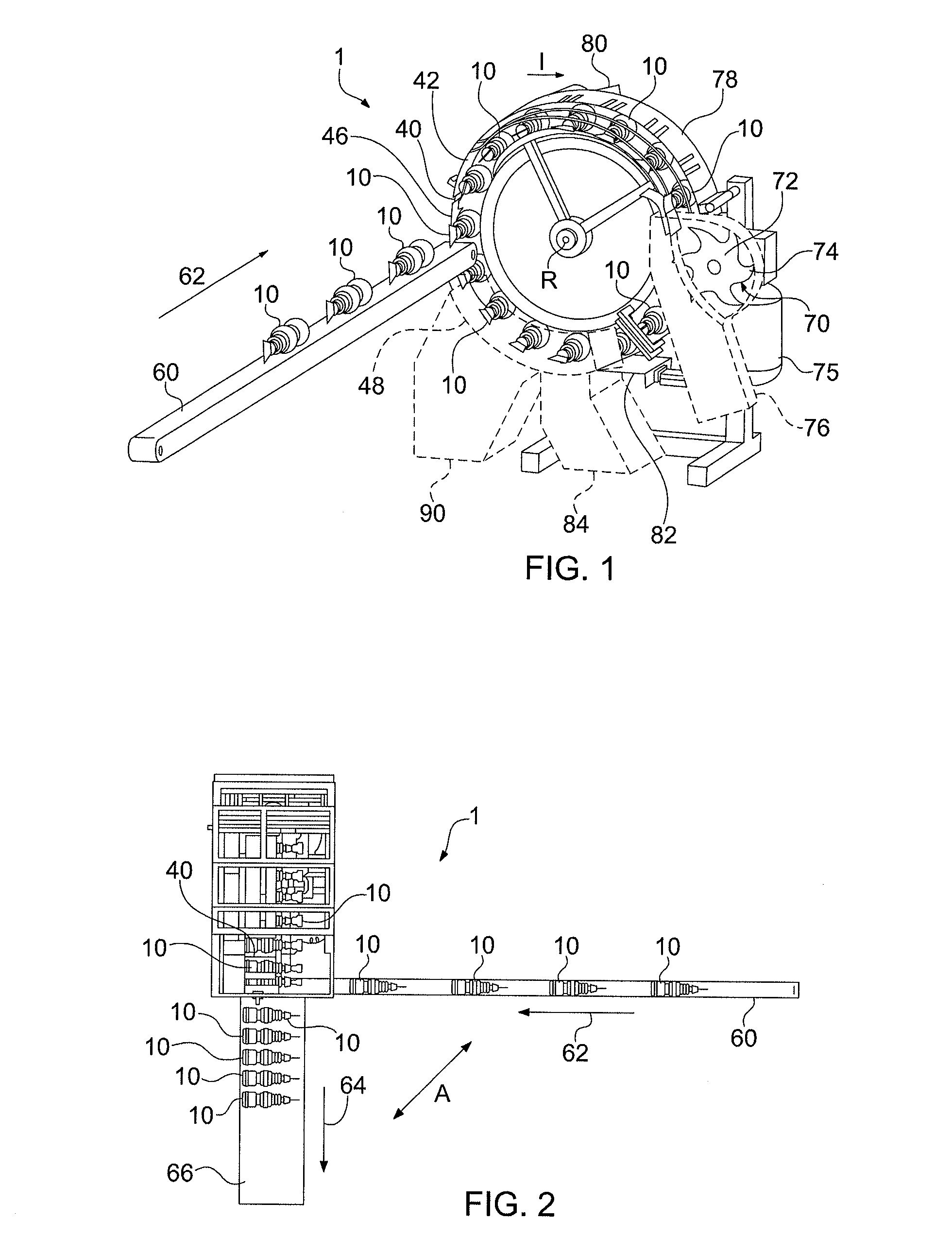
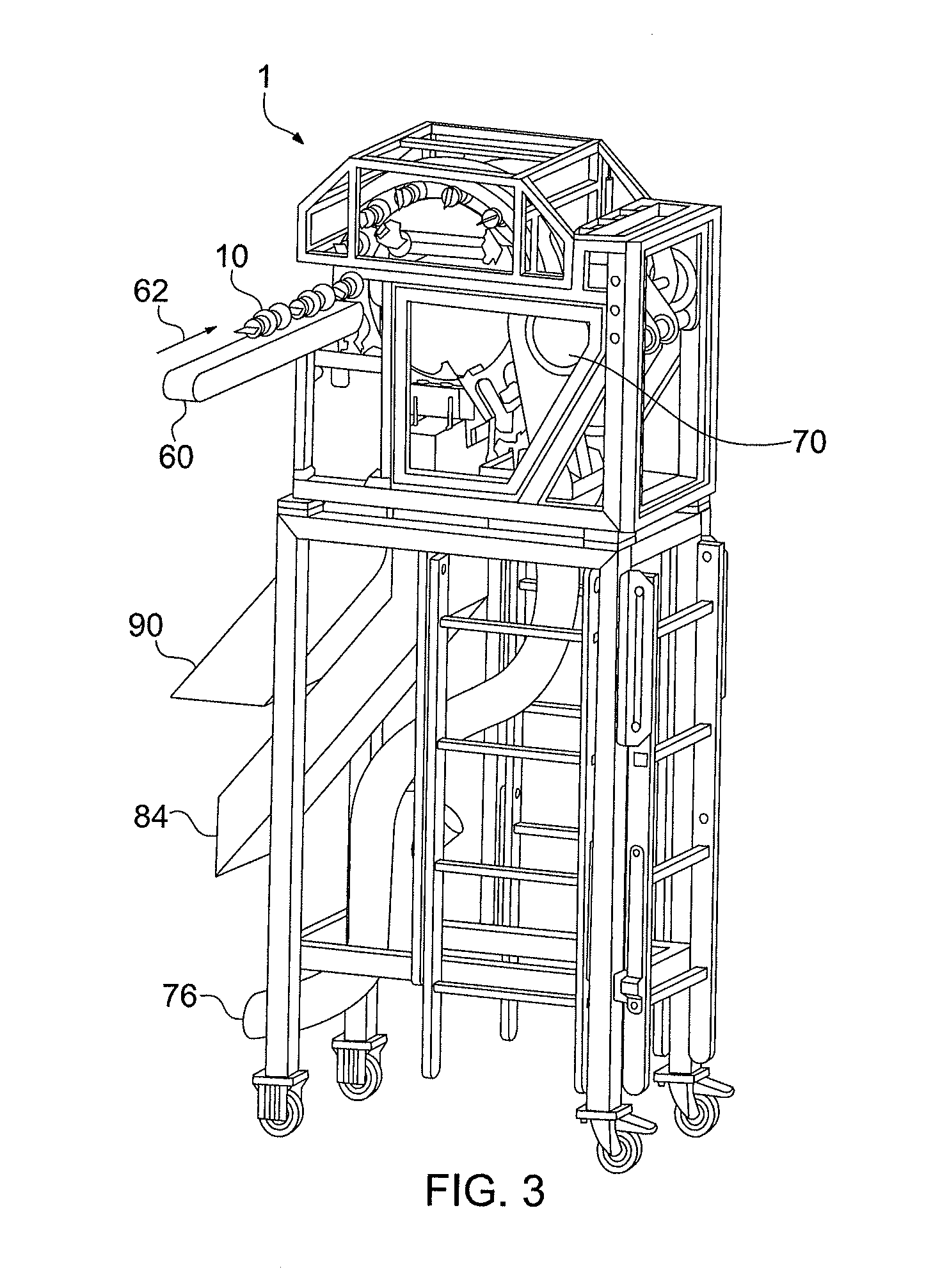
The present invention is an automatic rotary transfer apparatus for conveying a plurality of lightweight articles at a high speed. The apparatus includes a carriage ring with a plurality of cavities, a vacuum device to help position and hold each article in its respective cavity, and at least one sensor to determine if each cavity is occupied by the single article. The apparatus also includes a drive assembly to help ensure high precision and repeatability in high speed, to index and rotate the carriage ring about a central axis of rotation and synchronized to a continuous stream of the plurality of articles from an upstream operation. The apparatus allows for the conveyance of lightweight articles formed from an upstream blow molding operation, such as hollow or empty bottles or containers, in a reliable and consistent manner. It can also perform a number of different functions in a single rotation of the carriage ring, such as de-flashing, trimming, inspection, separating, hook closing, and combinations of such operations, which makes the apparatus more efficient and cost-effective than multiple specialized devices for each function.

Problems solved by technology

Unlike the ease at which heavy articles (e.g., filled bottles) can be handled, positioned, conveyed, and reoriented, lightweight articles are difficult to do the same.
Direct contact between the bottles may be detrimental.
For example, bottles produced through a blow molding operation may not be fully set or hardened or may have a glossy surface during transport; contact with adjacent bottles may cause the bottles to stick to one another resulting in damage to the bottles.

Method used


Image

  • Automatic rotary transfer apparatus and method
  • Automatic rotary transfer apparatus and method
  • Automatic rotary transfer apparatus and method

Examples


Embodiment Construction

[0035]The present invention provides for a high-efficiency automatic rotary transport apparatus having a space-saving design. The rotary transfer apparatus is able to handle and accurately position articles moving at a high rate of speed, even in the case of bottles which are empty and lightweight (e.g., as compared to filled bottles or heavier articles). The automatic rotary transport apparatus saves space by having only a small footprint in which to change the direction of transport of the articles and, optionally, to re-orient the articles. The apparatus is also able to perform a number of different functions in a single rotation of the apparatus in a precise and consistent manner. The automatic rotary transport apparatus may incorporate additional functionality, such as de-flashing, quality inspection, trimming or cutting operations, and folding or bending operations, for example, in a single rotation of the apparatus. The present invention also provides a related method for per...


PUM

PropertyMeasurementUnit
Fractionaaaaaaaaaa
Angleaaaaaaaaaa
Massaaaaaaaaaa

Abstract

An automatic rotary transfer apparatus and method for conveying a plurality of lightweight articles, such as empty bottles, at a high speed and, optionally, providing at least one additional function, such as de-flashing, trimming, or inspecting, in a single rotation of the rotary transfer apparatus. The apparatus includes a carriage ring having an outer perimeter defining a plurality of cavities spaced along the outer perimeter. Each cavity is adapted to receive a single article. A drive assembly indexes and rotates the carriage ring about a central axis of rotation and is synchronized to a continuous stream of the plurality of articles from an upstream operation, such as blow molding. The apparatus may further include a modification device, such as a de-flasher or trimmer, and an inspection station with a sensor for discharging damaged or imperfect articles, which performs the functions in a single rotation of the carriage ring.

Description

TECHNICAL FIELD[0001]The present invention relates generally to rotary transfer apparatus and methods of transporting and processing containers, bottles, and like objects.BACKGROUND OF THE INVENTION[0002]When articles, such as bottles, are manufactured, the articles may need to undergo a number or series of process steps, such as molding, trimming, finishing, packaging, and the like. Thus, the articles may need to be transported between operations, for example, using a conveyor. Such conveyance apparatus and systems may take up a large amount of floor space or footprint and may not be able to convey the articles in the desired direction or orientation.[0003]In particular, problems arise when the articles need to change from one direction of travel or orientation to another. In typical bottle conveyance systems, a conveyor running in one direction drops the bottles (e.g., through a drop box) onto a bucket conveyor running in a different direction. There is a high rate of error, howev...

Claims


Application Information

Patent Timeline
IPC IPC(8): B65G17/46
CPCB65G17/46B29C49/72B65G29/02B65G47/24B65G47/848B29C49/42069B29C49/4238
Inventor WOINSKI, GRZEGORZSTRUPINSKI, SLAWOMIR
Owner GRAHAM PACKAGING CO LP
Learn More