Antennas using over-coupling for wide-band operation

Active Publication Date: 2014-08-28
HONG KONG APPLIED SCI & TECH RES INST
View PDF6 Cites 3 Cited by
  • Summary
  • Abstract
  • Description
  • Claims
  • Application Information

AI Technical Summary

Benefits of technology

The present invention is about using multiple antenna elements to create a wide-band operation. This is achieved by over-coupling the elements, which splits the resonate frequency of the elements into multiple frequency bands. This helps the antenna system to provide wider bandwidth, even with narrow-band elements. The technical effect is a more efficient use of multiple antenna elements to achieve wide-band operation.

Problems solved by technology

Although the currently established SAR requirements are generally easily met by communications devices implementing narrow-band antenna configurations, such narrow-band antenna configurations are often not well suited for use with respect to many modern communications devices.
Unfortunately, meeting the SAR requirements imposed by one or more government entity, particularly the SAR requirements of the FCC, is problematic when wide-band antenna configurations are utilized.
Although the foregoing technique has generally been acceptable for implementing wide-band antenna configurations in personal communications systems which meet the various SAR requirements, the solution is not without disadvantage.
For example, should a need arise to implement more than one transmit antenna, such as for multiple-input multiple-output (MIMO) protocols, the additional antenna elements would be located more near to the area in which SAR measurements are made, thus likely resulting in an inability to comply with SAR requirements.
However, each such alternative is likewise associated with disadvantages.
In order to provide a wide-band antenna configuration using such meta-materials, the antenna element must generally be relatively large, thereby presenting a solution which is problematic with respect to the relatively small size of personal communication devices.
However, such fast switching adaptive circuits are neither inexpensive nor small, thereby providing a solution which is not well suited for personal communications devices.
However, such solutions are generally objectionable to the users of the communications devices as the performance of the device is lessened.

Method used


Image

  • Antennas using over-coupling for wide-band operation
  • Antennas using over-coupling for wide-band operation
  • Antennas using over-coupling for wide-band operation

Examples


Embodiment Construction

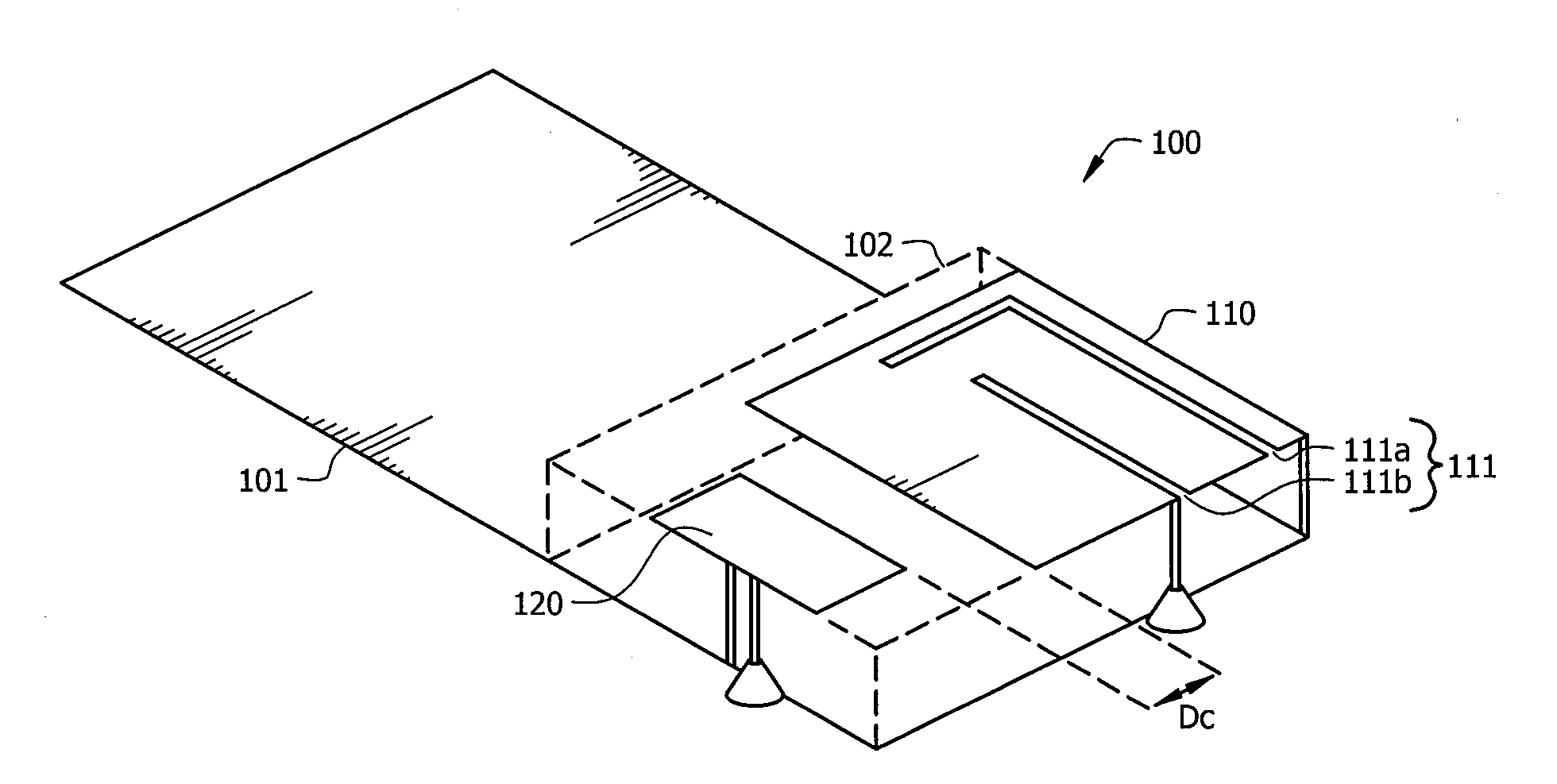
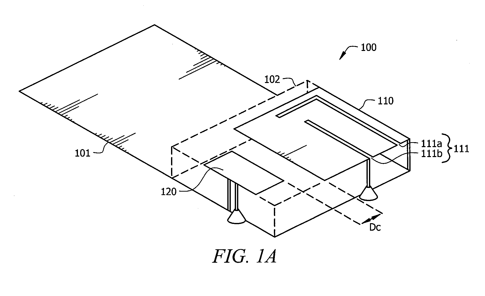
[0022]FIG. 1A shows over-coupled antenna system 100 according to embodiments of the invention. Over-coupled antenna system 100 of the illustrated embodiment implements over-coupling between antenna elements 110 and 120 thereof for effectively providing wide-band operation. In particular, in the over-coupling configuration shown in FIG. 1A, adaptation to antenna element 110, here an “influencing antenna element”, results in substantial operational frequency band adaptation to antenna element 120, here a “respondent antenna element” of over-coupled antenna system 100.

[0023]Although various antenna element configurations may be utilized according to embodiments of the invention, to aid in understanding the concepts herein the illustrated embodiment shows a configuration in which antenna elements 110 and 120 are planar antenna elements. Accordingly, antenna elements 110 and 120 are each illustrated as planar conductors disposed in correspondence with a ground plane, shown here as ground...


PUM


Abstract

Systems and methods in which antenna system configurations use over-coupling between a plurality of antenna elements for effectively providing wide-band operation are shown. Such over-coupling comprises a multiple antenna element configuration in which adaptation to one antenna element (e.g., an influencing antenna element) results in substantial operational frequency band adaptation to a second antenna element (e.g., a respondent antenna element). Over-coupling results in a frequency split at the second antenna, whereby the resonate frequency of the antenna element is split into a plurality of frequency bands. By implementing such frequency splitting with respect to otherwise narrow band antenna elements, the over-coupled antenna system may be made to effectively provide wide-band operation.

Description

TECHNICAL FIELD[0001]The present invention relates generally to wireless communications and, more particularly, to antenna configurations using over-coupling between a plurality of antenna elements to provide wide-band operation.BACKGROUND OF THE INVENTION[0002]The use of wireless communications has become prevalent in modern society. Wireless systems are utilized daily by business, individuals, governments, etc. to provide voice and data communication. For example, cellular phones, particular “smart phones” having advanced processing as well as communication capabilities, are in widespread use daily by persons from all walks of life.[0003]With the proliferation of wireless communications there has been a rise in awareness of the potential for harm to human tissue from exposure to high levels of radiated energy. Accordingly, many governments have established limits on the amount of energy irradiated into a portion of the body of a user of a wireless device. The United States Federal...

Claims


Application Information

Patent Timeline
IPC IPC(8): H01Q21/30
CPCH01Q21/30H01Q5/40
Inventor ROWEL, CORBETT RAY
Owner HONG KONG APPLIED SCI & TECH RES INST
Why Eureka
Try Eureka