Power-supply unit

a power supply unit and power supply technology, applied in the direction of power conversion systems, dc-dc conversion, electrical apparatus, etc., can solve the problems of large quantity of electric charge stored, reduced voltage between the positive electrode and the negative electrode, and inability to supply enough electric power to the load uni

Inactive Publication Date: 2014-08-28
TOYOTA JIDOSHA KK
View PDF11 Cites 18 Cited by
  • Summary
  • Abstract
  • Description
  • Claims
  • Application Information

AI Technical Summary

Benefits of technology

[0016]With the above arrangement, when the above-described abnormal condition is detected, the second switching device is placed in the OFF state; therefore, the voltage between the terminals of the smoothing capacitor is not reduced, and electric power can continue to be supplied to the load unit.

Problems solved by technology

Thus, a large quantity of electric charge is stored in the smoothing capacitor.
However, if the switching device of the discharge portion is brought into a condition of a short-circuit fault, for example, the voltage between the positive electrode and the negative electrode is reduced; therefore, sufficient electric power cannot be supplied to the load unit.

Method used


Image

  • Power-supply unit
  • Power-supply unit
  • Power-supply unit

Examples


first embodiment

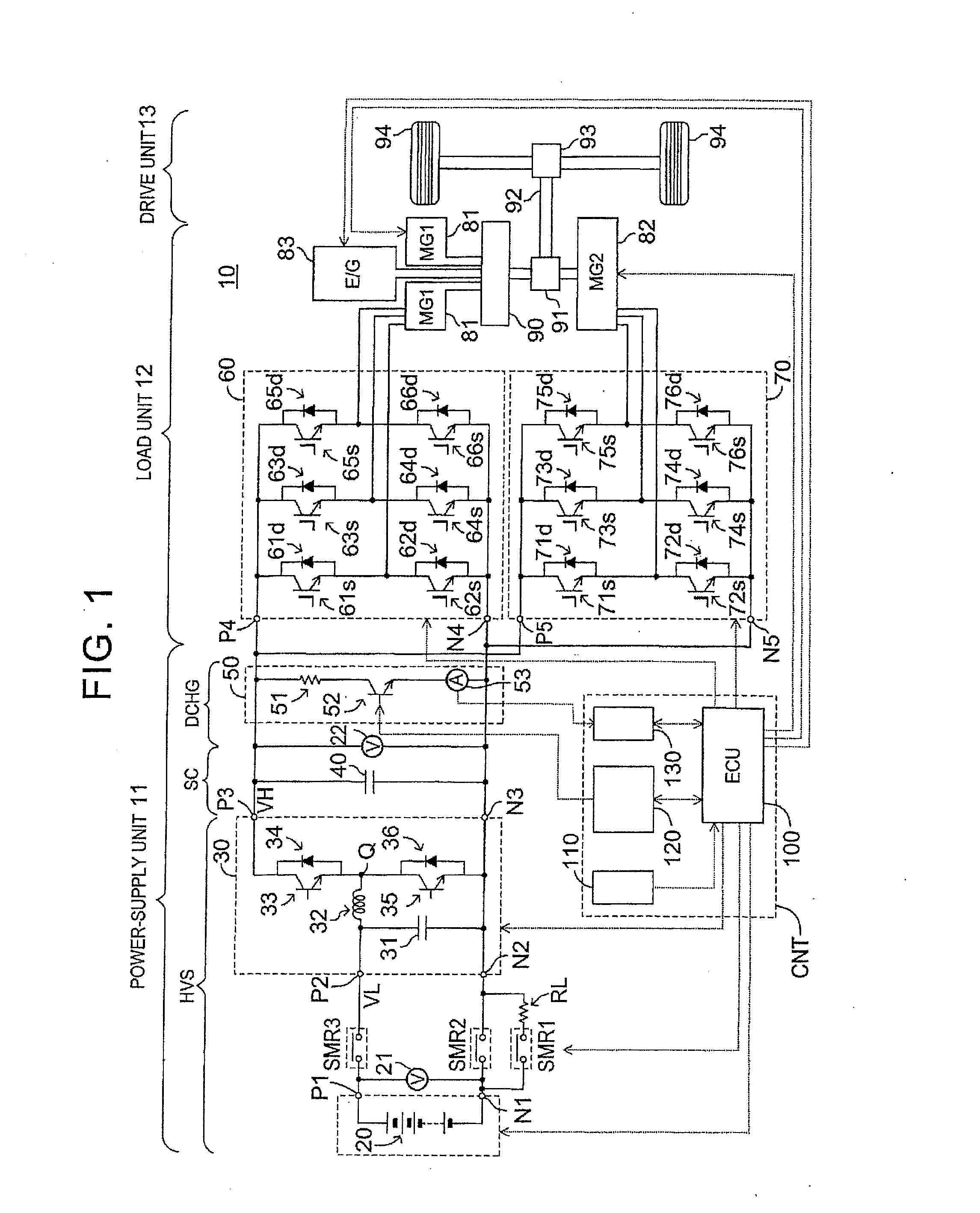
[0024](Configuration) As shown in FIG. 1, a power-supply unit (which will also be called “first power-supply unit”) 11 according to a first embodiment of the invention is installed on a hybrid vehicle (which will also be called “vehicle”) 10. Further, a load unit 12 and a drive unit 13 are installed on the vehicle 10.

[0025]The power-supply unit 11 includes a high-voltage source HVS, a smoothing capacitor portion SC, and a discharge portion DCHG.

[0026]The high-voltage source HVS includes a storage battery 20, a boost converter 30, and system main relays SMR1-SMR3.

[0027]The storage battery 20 is a chargeable / dischargeable secondary battery, which is a lithium-ion battery in this embodiment. The storage battery 20 generates DC power to a pair of storage-battery terminals P1, N1. The storage battery 20 is charged with voltage applied from the outside to the pair of storage-battery terminals P1, N1.

[0028]The boost converter 30 has a pair of low-voltage-side terminals P2, N2, and a pair o...

second embodiment

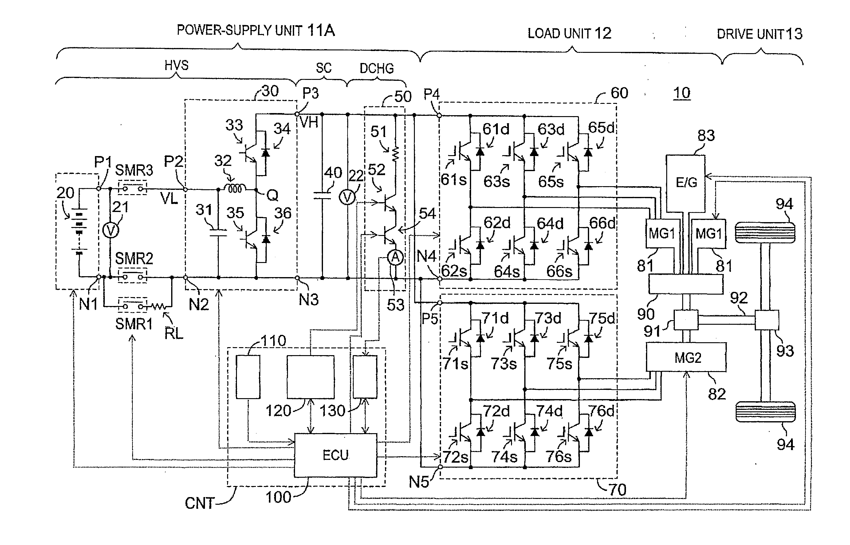
[0081](Configuration) Next, a power-supply unit 11A (which will also be called “second power-supply unit”) according to a second embodiment of the invention will be described. As shown in FIG. 4, the second power-supply unit 11A is applied to the hybrid vehicle 10, like the first power-supply unit 11. In the following description, the same reference numerals as used in the description of the first embodiment are assigned to the same or corresponding constituent elements or steps as those of the first embodiment.

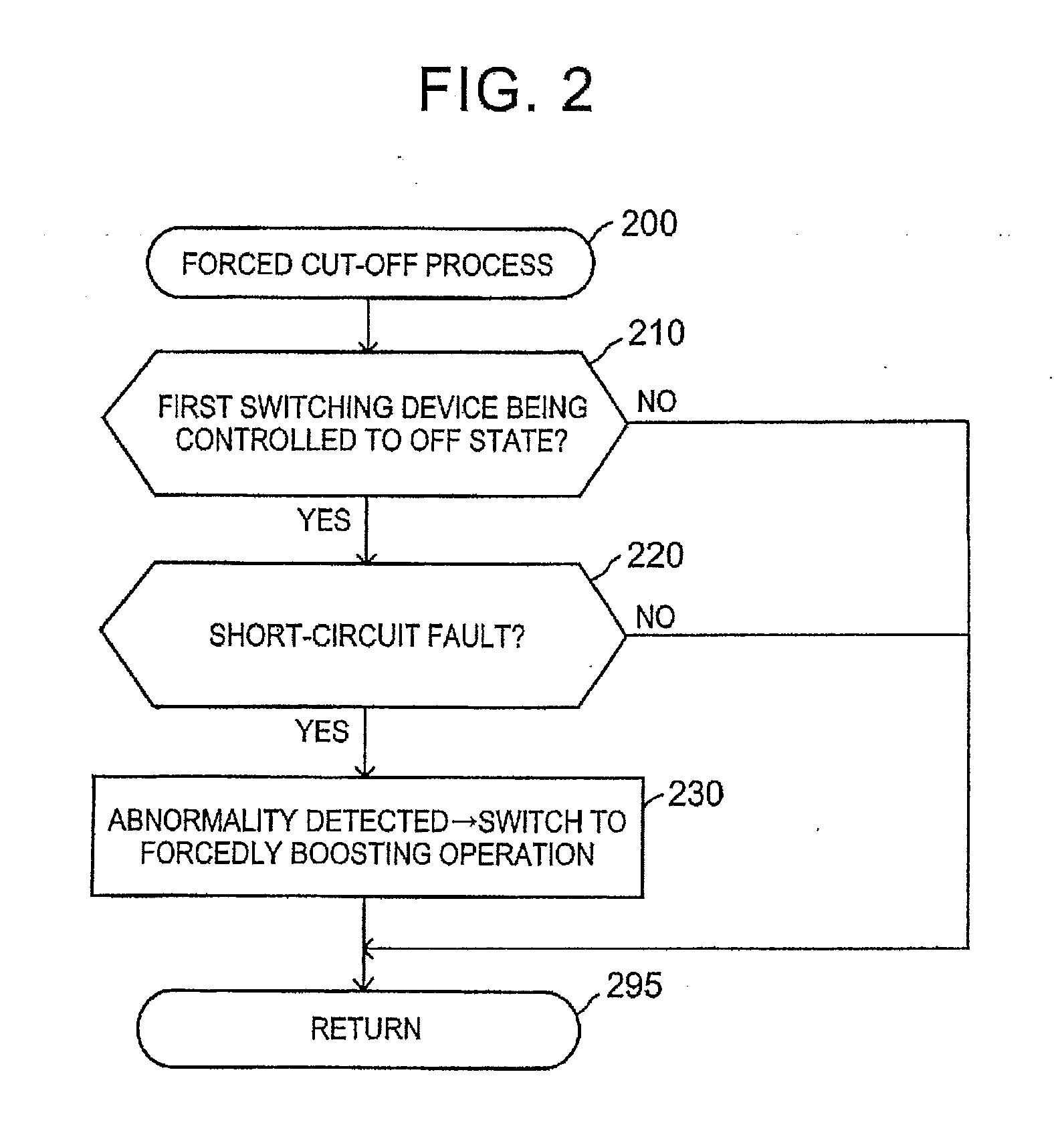
[0082]The second power-supply unit 11A is different from the first power-supply unit 11, only in that a second switching device 54 is provided in the discharge portion DCHG, and that, in the event of a short-circuit fault, the second switching device 54 is switched from an “ON” state to an “OFF” state, instead of execution of the forcedly boosting operation during a short-circuit fault. In the following, these differences will be mainly described.

[0083]The second switching de...


PUM


Abstract

A power-supply unit includes a high-voltage source that generates a high voltage between a positive electrode and a negative electrode, a smoothing capacitor connected between the positive electrode and the negative electrode, a discharge portion that includes a resistor and a first switching device connected in series with each other, and is connected between the positive electrode and the negative electrode, and a discharge control portion that controls the first switching device to one of an ON state and an OFF state. When an abnormal condition in which current flows through the resistor is detected while the discharge portion controls the first switching device so as to keep the first switching device in the OFF state, the high-voltage source is controlled so as to keep generating a given high voltage for fusing the resistor.

Description

INCORPORATION BY REFERENCE[0001]The disclosure of Japanese Patent Application No. 2013-034630 filed on Feb. 25, 2013 including the specification, drawings and abstract is incorporated herein by reference in its entirety.BACKGROUND OF THE INVENTION[0002]1. Field of the Invention[0003]The invention relates to a power-supply unit for supplying electric power to a load unit, such as a motor for driving a vehicle, and a motor for driving a machine, for example.[0004]2. Description of Related Art[0005]Generally, a power-supply unit for supplying electric power to a load unit, such as a driving motor, often includes a switching circuit, such as an inverter. Accordingly, the power-supply unit of this type often includes a smoothing capacitor. Since the smoothing capacitor is connected between a positive electrode and a negative electrode of the power-supply unit, the voltage between the opposite ends of the capacitor is relatively high. Thus, a large quantity of electric charge is stored in...

Claims


Application Information

Patent Timeline
Patent Type & Authority Applications(United States)
IPC IPC(8): H02H3/08
CPCH02H3/08H02M3/156H02M1/322H02M1/325
Inventor NOMURA, ATSUSHI
Owner TOYOTA JIDOSHA KK
Why Eureka
Try Eureka