System for Determining Position of Element

Active Publication Date: 2014-08-28
NOVO NORDISK AS
View PDF14 Cites 50 Cited by
  • Summary
  • Abstract
  • Description
  • Claims
  • Application Information

AI Technical Summary

Benefits of technology

[0027]Designing an electronic recording unit, that can automatically identify and recognise drug delivery devices with different contents will allow manufacturers a simpler and more cost efficient production and provide increased safety of the users.
[0028]Manufacturers will be able produce both drug delivery devices and electronic recording units in a more cost efficient way, since fewer distinguishing marks (and thus fewer parts) is needed to be able to distinguish between different contents and fewer different electronic recording units are necessary, the more devices with different contents each electronic recording unit is able to handle.
[0029]The safety of the users is increased since the electro

Problems solved by technology

However, such logs are normally kept in handwritten notebooks, from the logged information may not be easily uploaded to a computer for data processing.
A missing or erroneous record in the log results in a misleading picture of the injection history and thus a misleadi

Method used


Image

  • System for Determining Position of Element
  • System for Determining Position of Element
  • System for Determining Position of Element

Examples


example 1

[0084]In this example, the above algorithm is applied to a system with 24 axial displacements and with three ring-mounted sensors monitoring the magnet position.

[0085]The dipole field model output is derived in each sensors position for magnet that is rotated to a position in 15° steps with 0.1488 mm axial displacement for each step. This can be stored in the system as the nominal model. An example of such a computer generated look-up table is shown in table 1 and illustrated in FIG. 6A.

TABLE 1Example of look-up table of the nominal modelAngularAxialRodPos.Pos.SensorSensorSensorSensorSensorSensorSensorSensorSensorposition(Deg.)(mm)1 X1 Y1 Z2 X2 Y2 Z3 X3 Y3 Z000.0001.9030.358−0.4140.122−1.7210.334−0.7880.8610.0801150.1492.0570.067−0.393−0.234−1.5030.223−0.4471.2660.1702300.2982.072−0.232−0.342−0.583−1.1680.116−0.0661.6000.2263450.4461.940−0.517−0.272−0.903−0.7360.0230.3281.8350.2484600.5951.666−0.768−0.192−1.169−0.239−0.0460.7071.9520.2395750.7441.267−0.968−0.116−1.3640.290−0.0881.04...

example 2

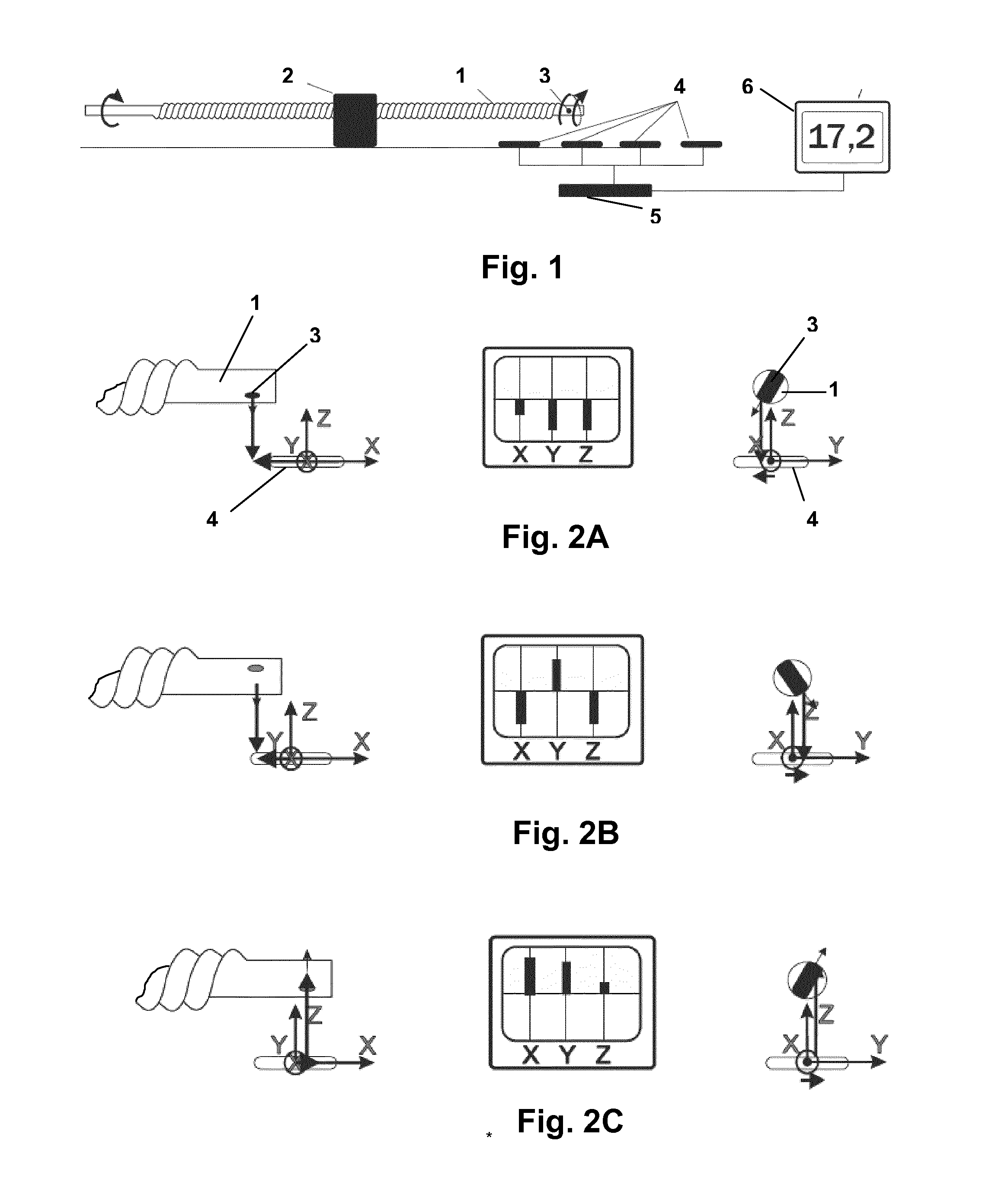
[0127]For a model corresponding to FIG. 1 with two axially arranged sensors, a piston rod was rotated from 0-150° and measurements were made for every 7.5° of rotation. The measurements listed below in tables 1 and 2 were made using an experimental set-up using Honeywell HMC5883L 3-axis magneto sensors. Based on this, a table of all axis values of all difference vectors for each measured angular (and thus linear) position can then be set up for the entire range of operation and stored in the system. An example of such a table is shown in table 1.

TABLE 6Example of look-up table of difference-vector axis' values and corresponding positions of a threaded rodRodPositionAngularAxial(x 0.5Pos.Pos.SensorSensorSensorSensorSensorSensorDifferenceDifferenceDifferenceunits)(Deg.)(mm)1 X1 Y1 Z2 X2 Y2 Z2-1 X2-1 Y2-1 Z00.00.000−155.9143.2295.9−133.793.8170.222.2−49.4−125.717.50.074−156.6143.5295.9−133.494.3169.923.2−49.2−126.0215.00.149−156.7144.2295.1−133.295.2168.723.5−49.0−126.4322.50.223−156.6...

examples

[0156]1. A drug delivery system, comprising:

(a) a drug delivery device 610, 710, 810 comprising:[0157]a reservoir containing a drug,[0158]a drug expelling mechanism for expelling drug from the reservoir, and[0159]an identifier 611, 711, 811 representing information for the specific drug type contained in the reservoir or the specific drug delivery device,

(b) a capture assembly 601, 701, 801 releasably mountable on the drug delivery device, comprising:[0160]an electronically controlled capturing system for capturing data representing a property related to the amount of drug expelled from the reservoir by the expelling means,[0161]electronically controlled means 603, 703, 803 for capturing information from the identifier,[0162]logging means adapted to create a log for amounts of drug expelled from the reservoir based on captured data,

wherein the log is created for a given identifier.

2. A drug delivery system as in example 1, wherein the identifier represents a given specific type of d...


PUM


Abstract

System comprising a sensor assembly (3, 4, 5, 6) adapted to measure a magnetic field, and a moveable element (1) adapted to be moved relative to the sensor assembly between two positions by a combined axial and rotational movement, the rotational movement having a pre-determined relationship to the axial movement. A magnet (3) is mounted to the moveable element and configured to generate a spatial magnetic field which relative to the sensor assembly varies corresponding to both the axial and rotational movement of the magnet and thus the moveable element. A processor is configured to determine on the basis of measured values for the magnetic field an axial position of the moveable element.

Description

[0001]The present invention relates to systems and methods for detecting the position of a moveable element. The invention addresses the issue of determining the axial and / or rotational position of an element which is moved both axially and rotationally. In a specific aspect, the invention addresses the issue of determining the axial position of an element which is moved corresponding to a threaded relationship between the moveable element and a further element.BACKGROUND OF THE INVENTION[0002]In the disclosure of the present invention reference is mostly made to drug delivery devices comprising a threaded piston rod, such devices being used e.g. in the treatment of diabetes by delivery of insulin, however, this is only an exemplary use of the present invention.[0003]Drug Injection devices have greatly improved the lives of patients who must self-administer drugs and biological agents. Drug Injection devices may take many forms, including simple disposable devices that are little mo...

Claims


Application Information

Patent Timeline
IPC IPC(8): A61M5/315G01B7/30
CPCA61M5/31568G01B7/30A61M2005/3126A61M5/1452A61M5/24A61M5/31525A61M5/31533G01D5/145G01R33/0206A61M2205/3317A61M2205/6054G01D18/004G01D18/008A61M2209/086A61M2205/3389G01D2205/22
Inventor LARSEN, ANDRESOERENSEN, HENRIK RIEHMOLESEN, LAURITS HOEJGAARDKRUSELL, NIKOLAJ FROGNERANDERSEN, JENS CHRISTIAN
Owner NOVO NORDISK AS
Why Eureka
Try Eureka