Stator vane row

a stator vanes and stator blade technology, applied in the field of annular rows of stator vanes, can solve the problems of undesirable non-uniform velocity and temperature distribution between stator blades and high-pressure turbine rotor blades of gas turbine engines, and detrimental to aerodynamic performance,

Active Publication Date: 2014-09-04
ROLLS ROYCE PLC
View PDF5 Cites 13 Cited by
  • Summary
  • Abstract
  • Description
  • Claims
  • Application Information

AI Technical Summary

Benefits of technology

[0009]It would be desirable to provide stator vane arrangement whi...

Problems solved by technology

High pressure (HP) turbine rotor blades and stator vanes of gas turbine engines can be subject to undesirable non-uniform velocity and temperature distributions in the working gas exiting from the combustor.
However, the non-equal cooling for the two NGVs introduces a non-equal aerodynamic flow field, which may prove to be detrimental to aero-thermal performa...

Method used


Image

  • Stator vane row
  • Stator vane row
  • Stator vane row

Examples


Embodiment Construction

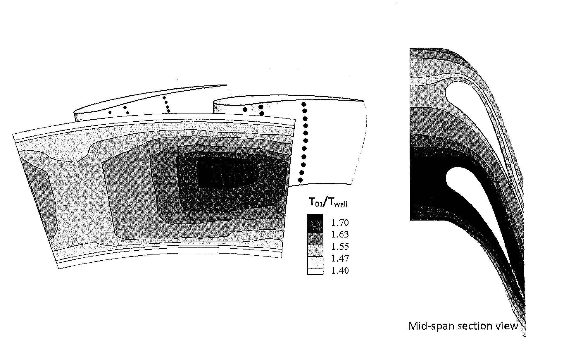
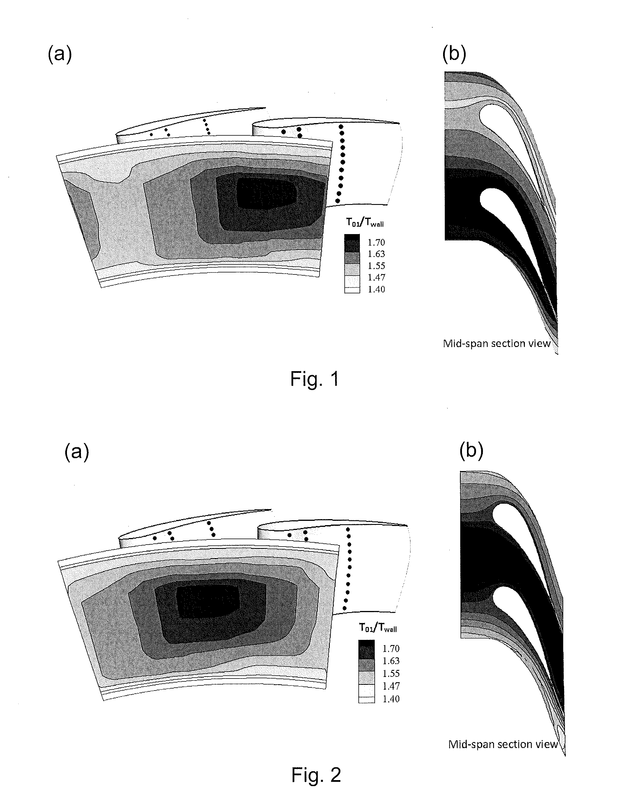
[0032]Each aerofoil member of a gas turbine engine (e.g. blade or vane) has a leading edge, a trailing edge, a pressure surface and a suction surface. Transverse cross sections through an aerofoil member provide respective aerofoil sections. Typically the leading and trailing edges of the aerofoil member are not straight lines. Thus, we define the “span line” of a leading or trailing edge as the straight line connecting the end points of the edge, e.g. at respective endwalls. Further we define the “midspan position” of a leading or trailing edge as the position on that edge which is closest to the midpoint of its span line. We also define the “midspan aerofoil section” as the aerofoil section of the aerofoil member which contains the midspan positions of the leading and trailing edges. Indeed, when we state herein that a parameter is “at midspan”, we mean that that parameter is being determined at the midspan aerofoil section.

[0033]Features of the geometry of the aerofoil member can...


PUM


Abstract

In a gas turbine engine, each vane has pressure and suction surfaces extending radially from an inner to outer endwall of an annular working gas engine passage, and extending axially from a leading to a trailing edge of the vane. Each vane has transverse sections providing respective aerofoil sections. Neighbouring vanes are arranged in unequally-shaped pairs in which either: (i) the first vane of each pair exhibits compound lean, and the second vane of the pair exhibits reverse compound lean or has substantially no tangential lean, (ii) the first vane of each pair has substantially no tangential lean, and the second vane of the pair exhibits reverse compound lean, or (iii) the first vane of each pair exhibits reverse compound lean, and the second vane of the pair exhibits greater reverse compound lean. Within each unequally-shaped pair the first vane is on the pressure surface side of the second vane.

Description

FIELD OF THE INVENTION[0001]The present invention relates to an annular row of stator vanes for a gas turbine engine.BACKGROUND OF THE INVENTION[0002]High pressure (HP) turbine rotor blades and stator vanes of gas turbine engines can be subject to undesirable non-uniform velocity and temperature distributions in the working gas exiting from the combustor. In particular, circumferentially spaced “hot streaks” can be formed in the working gas, each streak extending downstream and originating from one of the circumferentially arranged fuel injectors of the combustor[0003]Circumferential non-uniform temperature distribution can affect the heat load on the blades in both the first row of nozzle guide vanes (NGVs) and the following rotor blade row.[0004]A design parameter, termed “clocking”, that can influence the NGV heat load is the relative circumferential positioning between the peak temperature of a combustor exit temperature profile (i.e. the centre of a hot streak) and a given NGV....

Claims


Application Information

Patent Timeline
IPC IPC(8): F01D9/04
CPCF01D9/041F01D5/141F01D5/145F01D5/146F05D2250/38F05D2250/73
Inventor HE, LIRAHIM, AMIRKHANAL, BIDURROMERO, EDUARDO
Owner ROLLS ROYCE PLC
Why Eureka
Try Eureka