Infrared detector and infrared image sensor including the same
a technology of infrared detector and infrared image sensor, which is applied in the direction of optical radiation measurement, instruments, thermoelectric devices, etc., can solve the problems of limiting the increase of filling factor and increasing the thermal loss of infrared absorbers
- Summary
- Abstract
- Description
- Claims
- Application Information
AI Technical Summary
Benefits of technology
Problems solved by technology
Method used
Image

Examples
Embodiment Construction
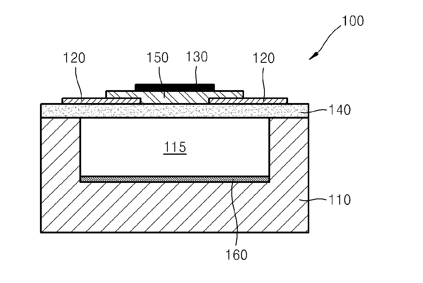
relate to infrared detectors and infrared image sensors, and more particularly, to a thermopile type infrared detector and an infrared image sensor including the same.
[0004]2. Description of the Related Art
[0005]An object having a certain temperature emits light in a particular wavelength band in accordance with black body radiation. Peripheral objects at room temperature emit infrared rays in wavelength bands ranging from about 8 to about 14 μm. To detect these emitted infrared rays, uncooled infrared detectors are frequently used. Generally, uncooled infrared detectors may be classified into bolometer type infrared detectors that use a resistance change of a material according to infrared rays incident thereon, pyroelectric infrared detectors using a polar change of a material according to infrared rays incident thereon, and thermopile type infrared detectors using an electromotive force change of a material according to infrared rays incident thereon. Bolometer type infrared dete...
PUM
 Abstract
Description
Claims
Application Information
 - R&D
- Intellectual Property
- Life Sciences
- Materials
- Tech Scout
- Unparalleled Data Quality
- Higher Quality Content
- 60% Fewer Hallucinations
Browse by: Latest US Patents, China's latest patents, Technical Efficacy Thesaurus, Application Domain, Technology Topic, Popular Technical Reports.
© 2025 PatSnap. All rights reserved.Legal|Privacy policy|Modern Slavery Act Transparency Statement|Sitemap|About US| Contact US: help@patsnap.com