Hold-up time enhancement circuit for llc resonant converter

a technology of resonant converters and enhancement circuits, which is applied in the direction of electric variable regulation, process and machine control, instruments, etc., can solve the problems of low power density, high cost, and significant reduction in hold-up time, so as to increase bulk capacitance or sacrificing efficiency, the effect of reducing the hold-up tim

Active Publication Date: 2014-09-04
ASTEC INT LTD
View PDF6 Cites 7 Cited by
  • Summary
  • Abstract
  • Description
  • Claims
  • Application Information

AI Technical Summary

Benefits of technology

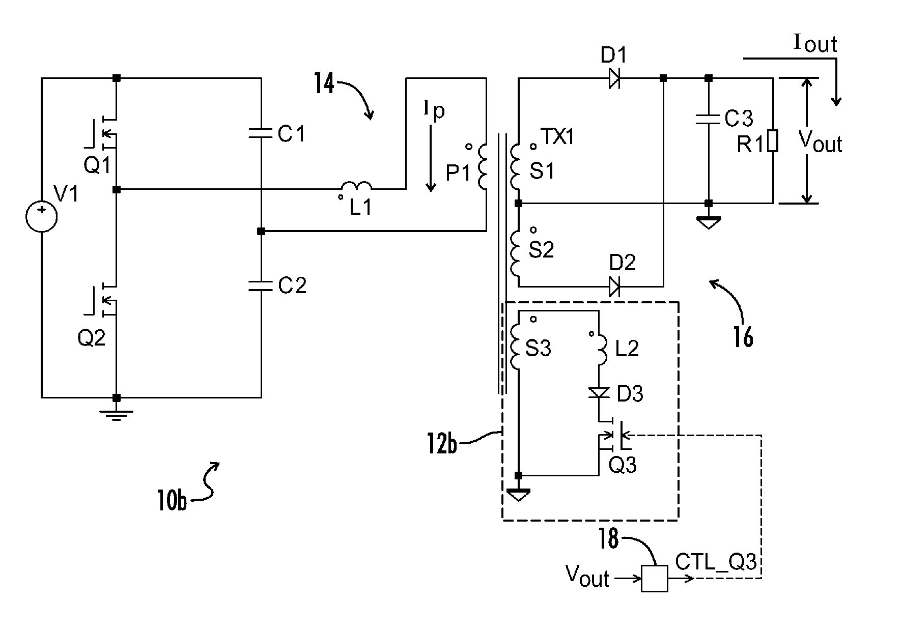
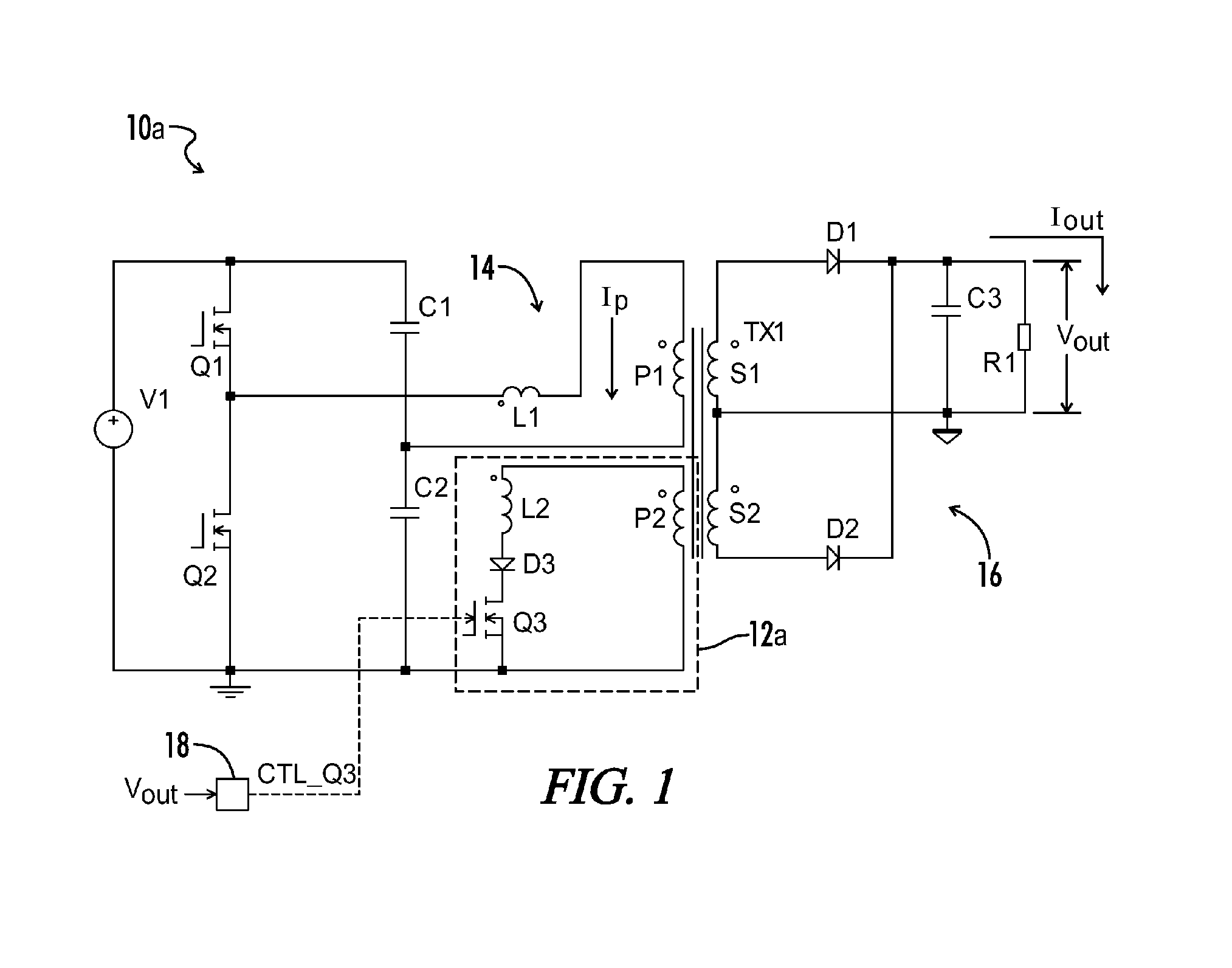
[0007]An open loop half-bridge LLC resonant power converter according to one aspect of the present invention includes circuitry to reliably increase hold-up time without increasing bulk capacitance or sacrificing efficiency.
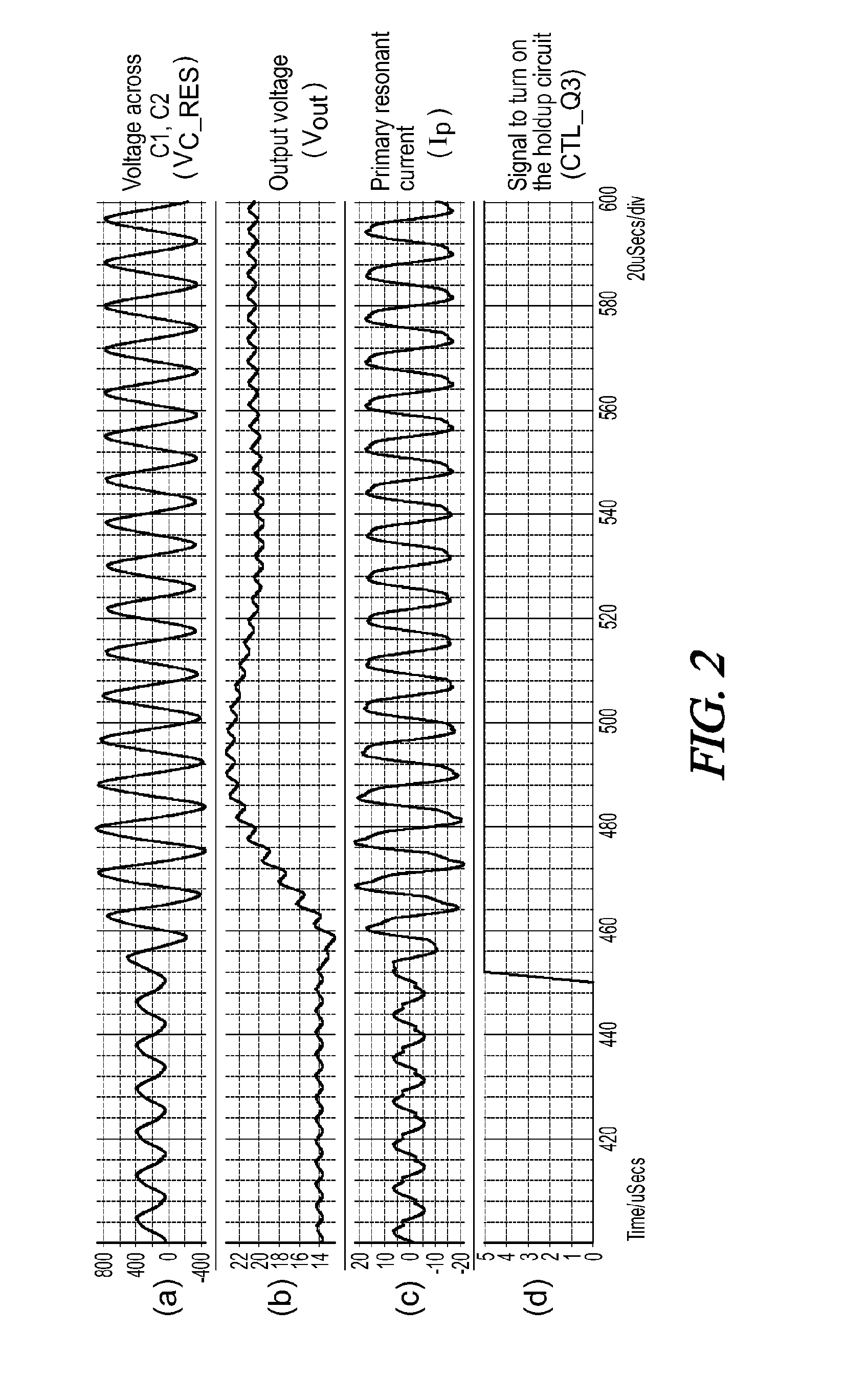
[0009]Generally stated, when the auxiliary circuit is enabled, current flows through the second inductor and the current is further coupled to the main transformer, wherein the gain of the resonant converter is increased and the output voltage maintained for a lower bulk voltage. Hence, increasing the hold-up time and maintaining high efficiency is achieved without requiring a larger, more expensive bulk capacitor in accordance with an objective of the present invention.

Problems solved by technology

However, there is a trade-off between the high efficiency and long hold-up time performance in a resonant converter.
However, the hold-up time will consequently decrease by a significant amount as well.
However, this results in problems of low power density and also higher cost.

Method used


Image

  • Hold-up time enhancement circuit for llc resonant converter
  • Hold-up time enhancement circuit for llc resonant converter
  • Hold-up time enhancement circuit for llc resonant converter

Examples


Embodiment Construction

[0024]Throughout the specification and claims, the following terms take at least the meanings explicitly associated herein, unless the context dictates otherwise. The meanings identified below do not necessarily limit the terms, but merely provide illustrative examples for the terms. The meaning of “a,”“an,” and “the” may include plural references, and the meaning of “in” may include “in” and “on.” The phrase “in one embodiment,” as used herein does not necessarily refer to the same embodiment, although it may.

[0025]The term “coupled” means at least either a direct electrical connection between the connected items or an indirect connection through one or more passive or active intermediary devices.

[0026]The term “circuit” means at least either a single component or a multiplicity of components, either active and / or passive, that are coupled together to provide a desired function.

[0027]The term “signal” as used herein may include any meanings as may be understood by those of ordinary...


PUM


Abstract

An open loop half-bridge LLC power converter includes circuitry to reliably increase hold-up time without sacrificing efficiency. An LLC resonant circuit includes resonant inductance, a primary transformer winding, and resonant capacitance. An auxiliary circuit includes an auxiliary transformer winding, an inductor, and a third switching element coupled in series. A controller is coupled across a voltage sensor and effective thereby to determine a holdup time condition. In a “normal” operating condition the controller generates switch driver signals to turn OFF the third switching element and disable the auxiliary circuit, and in a hold-up time condition the controller turns ON the third switching element and enables the auxiliary circuit wherein the output voltage is increased via current supplied from the auxiliary winding. In various embodiments the auxiliary winding may be an auxiliary primary or secondary, or a secondary to an auxiliary primary winding of a second transformer.

Description

CROSS-REFERENCES TO RELATED APPLICATIONS[0001]This application is a continuation of U.S. patent application Ser. No. 13 / 860,698 filed Apr. 11, 2013, and claims the benefit of U.S. Provisional Application No. 61 / 622,862 filed Apr. 11, 2012. The entire disclosures of the above applications are incorporated herein by reference.BACKGROUND OF THE INVENTION[0002]The present invention relates generally to power converters. More particularly, the present invention relates to gain enhancement circuitry for LLC resonant power converters wherein a hold-up time may be increased with minimal effect on efficiency.[0003]As market requirements for high efficiency have become more demanding, LLC resonant converters have correspondingly grown in popularity due to their high efficiency performance and their ability to achieve high power density. The 80 Plus Platinum certification standard requires greater than 94% efficiency at half load (50%) conditions. The 80 Plus Titanium standard requires 96% eff...

Claims


Application Information

Patent Timeline
Patent Type & Authority Applications(United States)
IPC IPC(8): H02M3/335
CPCH02M3/33523H02M3/3353Y02B70/10Y02P80/10H02M3/33507H02M1/0096
Inventor LEE, TAI KEUNG
Owner ASTEC INT LTD
Why Eureka
Try Eureka