Pre-collapsed capacitive micro-machined transducer cell with plug

a capacitive micromachine and transducer technology, applied in the field of pre-collapsed capacitive micromachine transducer cells, can solve the problems of inability to apply, inability to work with high-frequency cmut cells, retention members, etc., and achieve the effect of maintaining good transduction performance and filling available spa

Active Publication Date: 2014-09-04
KONINKLJIJKE PHILIPS NV
View PDF3 Cites 10 Cited by
  • Summary
  • Abstract
  • Description
  • Claims
  • Application Information

AI Technical Summary

Benefits of technology

[0023]In a further embodiment, the cell further comprising a cover layer arranged on the membrane and/or the plug. In this way a matching of the cell or membrane thickness to the specific resonance frequency of the cell can be achieved (providing acoustic property control) or to the operating range can be achieved. Also the cover layer may provide chemical passivation.
[0024]In another embodiment, the cell further comprises a first electrode on or in the substrate and/or a second electrode on or in the membrane. In this way a capacitive cell can be provided in an easy manner.
[0025]In a further embodiment, the second electrode is a ring-shaped electrode. In another embodiment, the cavity is a ring-shaped cavity. In any of these embodiments the cell can be a circular shaped cell. A circular shape is an advantageous cell shape because it provides a fairly good filling of available space and/or very few higher order vibrational modes, in particular vibrational modes that compete with the desired mode for transmitted energy or create undesired signals that obscure the desired received

Problems solved by technology

However, for high frequency cMUT cells a retention member as disclosed in WO 2010/097729 A1 cannot be applied, as the collapse pressure is very large and can easily exceed for example 5 Bar or even 10 Bar.
Th

Method used


Image

  • Pre-collapsed capacitive micro-machined transducer cell with plug
  • Pre-collapsed capacitive micro-machined transducer cell with plug
  • Pre-collapsed capacitive micro-machined transducer cell with plug

Examples


first embodiment

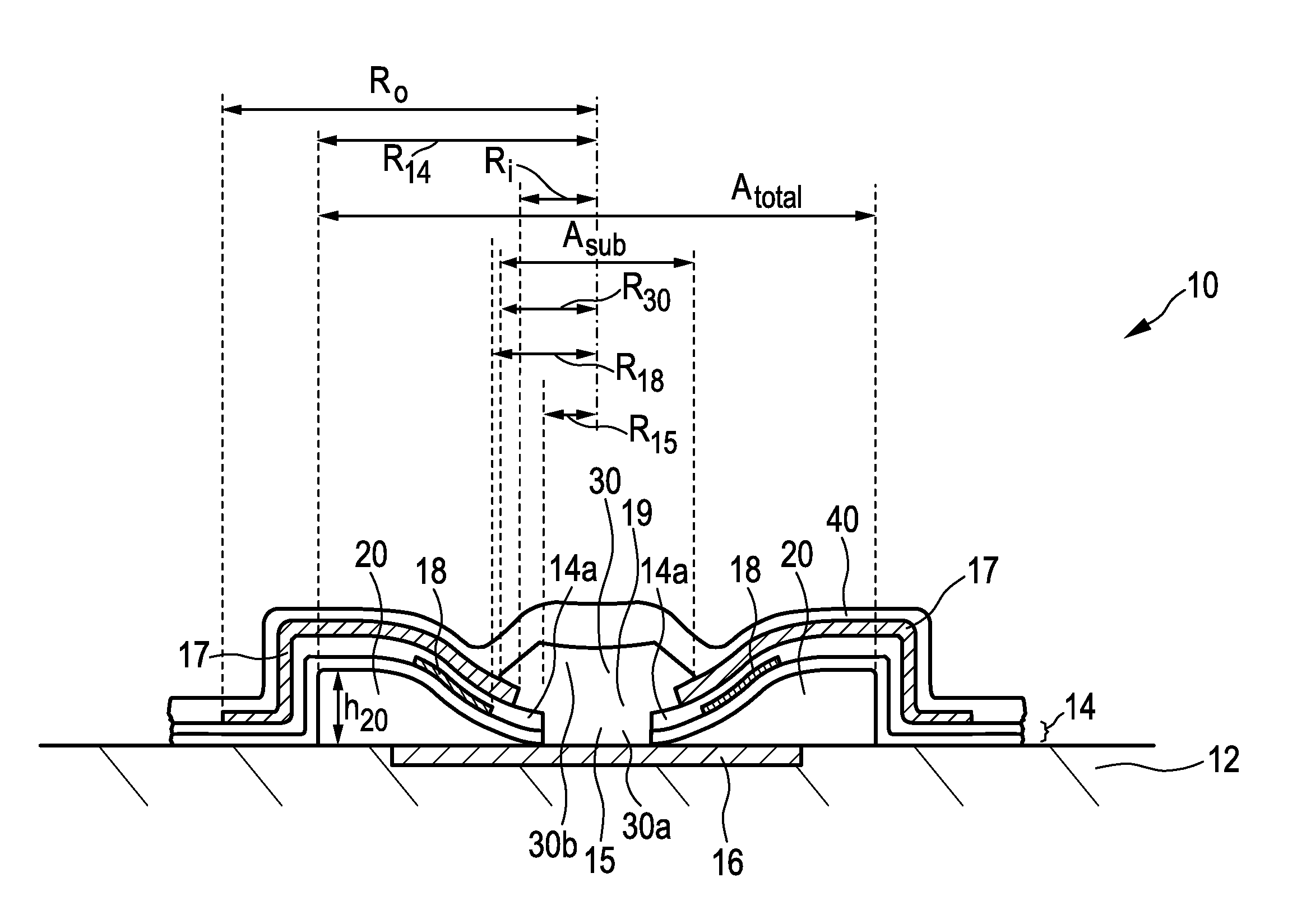
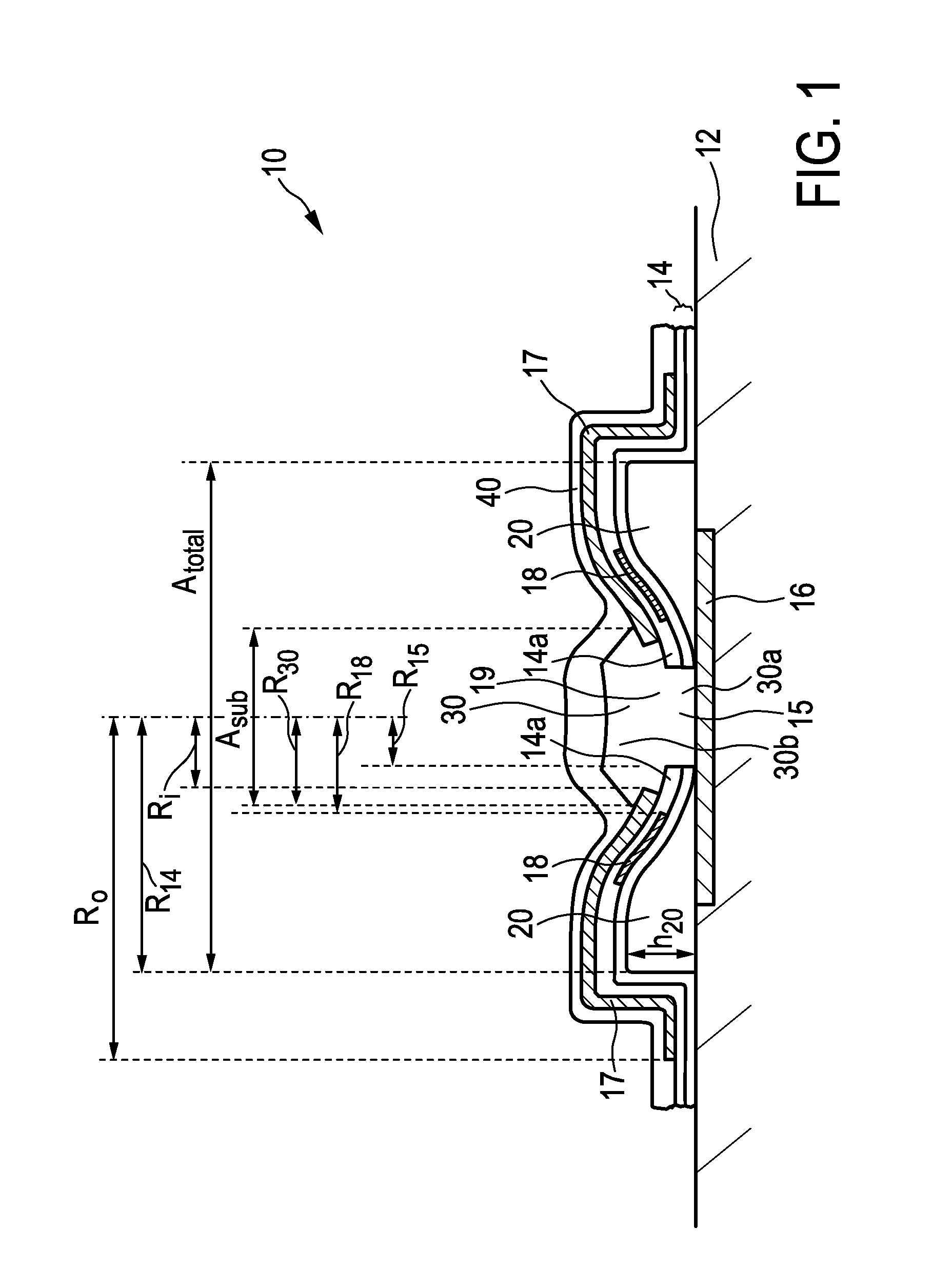
[0044]In FIG. 1, the position of the stress layer 17 also helps to provide the bending moment (or deflection) on the membrane in a direction towards the substrate 12. As can be seen in FIG. 1, the stress layer 17 extends beyond the total membrane area Atotal. The stress layer 17 further comprises a hole 19. The hole 19 in the stress layer 17 is in the centre or centre area of the total membrane area Atotal and is aligned with the hole 15 in the membrane 14. However, the hole 19 of the stress layer 17 is bigger than the hole 15 of the membrane 14.

[0045]For the choice of the stress layer material, many materials can have built-in stress when deposited, for example due to chemical composition, thermal shrinkage between the deposition temperature and the ambient temperature, or a combination of both. When a material layer is deposited, the deposition conditions can determine the stress value. For example, the stress layer can be deposited by sputtering (e.g. for deposition of a metal st...

second embodiment

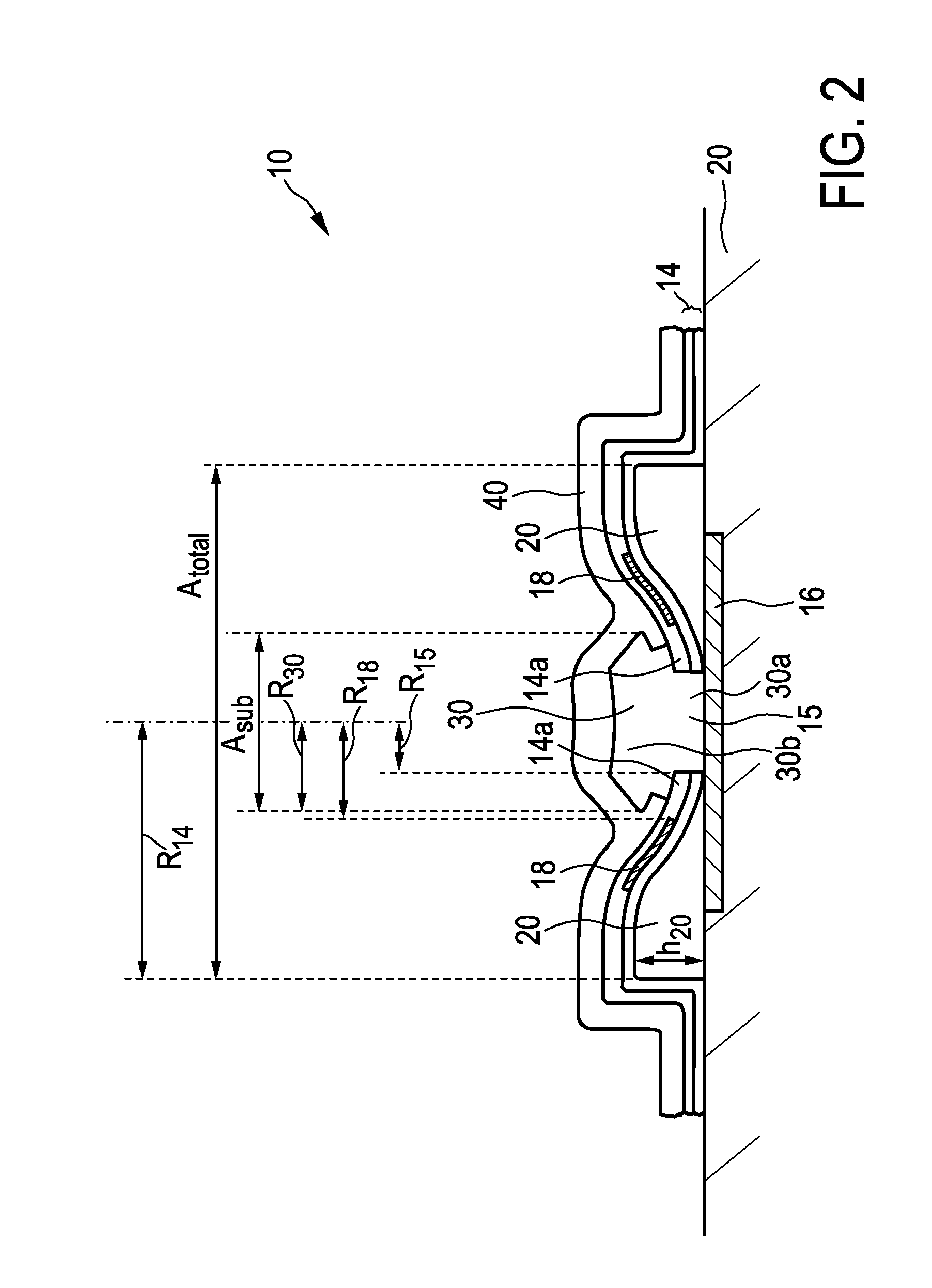
[0057]If in case of FIG. 2, a stress layer 17 is temporarily present (only during manufacturing) as explained above, the plug 30 can comprise a recess formed by removing the stress layer 17. This recess is a characteristic pattern in the plug 30 (in particular made of Nitride) in the form of a kind of overhang structure, caused by the removal of the stress layer 17.

[0058]The cell 10 of the first embodiment shown in FIG. 1 or the second embodiment shown in FIG. 2 further comprises a cover layer 40 arranged on the membrane 14 (or stress layer 17) and on the plug 30. The cover layer 40 is also movable or flexible, in order to be able to move or vibrate together with the membrane 14. However, it will be understood that such cover layer is optional. In case of a cMUT cell, the cover layer 40 provides a matching of the cell 10, or more specifically the thickness of the cell or membrane, to the specific resonance frequency of the cell. In case of a pressure sensor cell, the cover layer 40 ...


PUM

PropertyMeasurementUnit
Areaaaaaaaaaaa
Stress optical coefficientaaaaaaaaaa

Abstract

The present invention relates to a pre-collapsed capacitive micro-machined transducer cell (10) comprising a substrate (12), and a membrane (14) disposed above a total membrane area ((Atotal), wherein a cavity (20) is formed between the membrane (14) and the substrate (12), the membrane (14) comprising a hole (15) and an edge portion (14a) surrounding the hole (15), the edge portion (14a) of the membrane (14) being collapsed to the substrate (12). The cell further comprises a plug (30) arranged in the hole (15) of the membrane (14), the plug (30) being located only in a subarea (Asub) of the total membrane area (Atotal). The present invention further relates to a method of manufacturing such pre-collapsed capacitive micro-machined transducer cell (10).

Description

FIELD OF THE INVENTION[0001]The present invention relates to a pre-collapsed capacitive micro-machine transducer cell, in particular a capacitive micro-machined ultrasound transducer (cMUT) cell or a capacitive micro-machined pressure sensor cell, and a method of manufacturing the same.BACKGROUND OF THE INVENTION[0002]Recently micro-machined ultrasound transducers (MUT) have been developed. Micro-machined ultrasound transducers have been fabricated in two design a approaches, one using a semiconductor layer with piezoelectric properties (pMUT) and another using a membrane (or diaphragm) and substrate with electrodes (or electrode plates)forming a capacitor, so-called capacitive micro-machined ultrasound transducer (cMUT).[0003]A cMUT cell comprises a cavity underneath the membrane. For receiving ultrasound waves, ultrasound waves cause the membrane to move or vibrate and the variation in the capacitance between the electrodes can be detected. Thereby the ultrasound waves are transfo...

Claims


Application Information

Patent Timeline
IPC IPC(8): G10K11/18H04R31/00
CPCH04R31/00G10K11/18B06B1/0292Y10T29/49005
Inventor DIRKSEN, PETERDEKKER, RONALDHENNEKEN, VINCENT ADRIANUSLEEUWESTEIN, ADRIAANMARCELIS, BOUTFRASER, JOHN DOUGLAS
Owner KONINKLJIJKE PHILIPS NV
Why Eureka
Try Eureka