Supercharge Your Innovation With Domain-Expert AI Agents!

Motor control unit

Inactive Publication Date: 2014-09-11
JTEKT CORP
View PDF12 Cites 0 Cited by
  • Summary
  • Abstract
  • Description
  • Claims
  • Application Information

AI Technical Summary

Benefits of technology

The invention is about a motor control unit that can discharge electricity from a capacitor without causing excessive heat and damage to the motor and its components. The motor generates torque to carry out the discharge, and the angular velocity of the motor is controlled to prevent it from rotating too quickly. This prevents excessive load and stress on the motor and its components.

Problems solved by technology

However, provision of such a discharge circuit inevitably increases the size of the motor control unit.
Thus, resistance heating is likely to be a problem.
However, if electric power is supplied to the motor in a state where the clutch, which is the interrupting mechanism, is disengaged and thus the motor and the driven body are disconnected from each other to interrupt torque transmission, there is a possibility that the motor may rotate at an excessively high angular velocity (rotation angular velocity), unlike in a case where electric power is supplied to the motor in a state where the clutch is engaged and thus the motor and the driven body are connected to each other to allow torque transmission.
As a result, there is a possibility that an excessive burden may be placed on the motor itself and its peripheral components such as a bearing.

Method used


Image

  • Motor control unit
  • Motor control unit
  • Motor control unit

Examples


Embodiment Construction

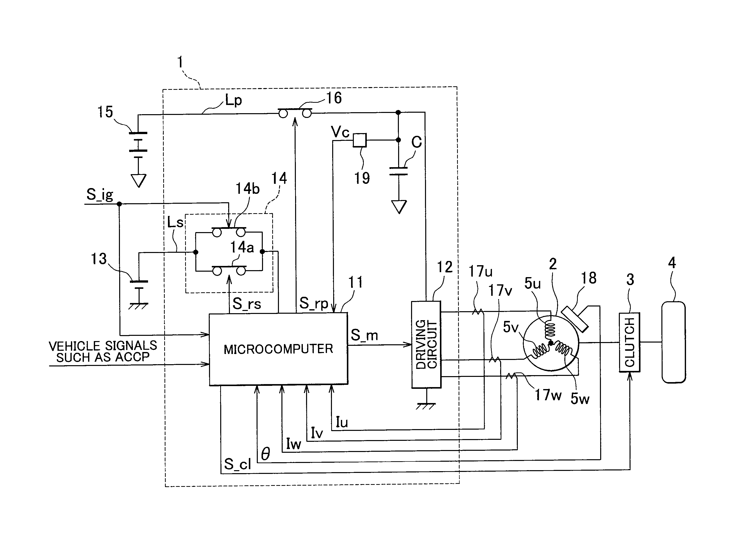
[0018]Hereinafter, a motor control unit 1 according to an embodiment of the invention will be described with reference to the accompanying drawings. The motor control unit 1 illustrated in FIG. 1 is used to control the operation of a motor 2 used as a driving source for travelling of an electric vehicle, a hybrid vehicle, or the like. The motor 2 is connected to a wheel 4, which is an example of a driven body, via a clutch 3 that may function as an interrupting mechanism. When the clutch 3 is engaged, the motor 2 and the wheel 4 are connected to each other to allow torque transmission. On the other hand, when the clutch 3 is disengaged, the motor 2 and the wheel 4 are disconnected from each other to interrupt torque transmission. As the motor 2 in the present embodiment, a brushless motor is adopted.

[0019]As illustrated in FIG. 1, the motor control unit 1 includes a microcomputer 11 that may function as a control circuit and that outputs a motor control signal S_m, and a driving cir...


PUM


Abstract

A motor control unit includes: a microcomputer that outputs a motor control signal; a driving circuit that supplies driving electric power to the motor based on the motor control signal; and a capacitor provided at an intermediate portion of a power supply line that connects the driving circuit and a driving power supply to each other. The microcomputer carries out electric discharge from the capacitor by supplying electric power generated by electric charges stored in the capacitor to the motor such that torque is generated by the motor and an angular velocity of the motor becomes less than or equal to a prescribed angular velocity, with torque transmission between the motor and the wheel interrupted by the clutch after a driving relay is turned off.

Description

INCORPORATION BY REFERENCE[0001]The disclosure of Japanese Patent Application No. 2013-046928 filed on Mar. 8, 2013 including the specification, drawings and abstract, is incorporated herein by reference in its entirety.BACKGROUND OF THE INVENTION[0002]1. Field of the Invention[0003]The invention relates to a motor control unit.[0004]2. Description of the Related Art[0005]In general, in a vehicle in which a motor is used as a driving source for vehicle travelling, such as an electric vehicle or a hybrid vehicle, a control unit for the motor is provided with a switch, such as a power supply relay, disposed at an intermediate portion of a power supply line (electric power supply path) that connects a driving circuit of the control unit and an external power supply to each other. When the switch is turned on and thus the power supply line is brought into conduction, electric power is supplied to the motor. Further, in such a motor control unit, a capacitor used to, for example, smooth ...

Claims


Application Information

Patent Timeline
IPC IPC(8): H02P23/00H02P27/04B60L3/00
CPCH02P27/04H02P23/0045B60L15/2054B60L50/40B60L58/10H02P6/20H02P23/16Y02T10/64Y02T10/70Y02T10/72B60L3/0046
Inventor UCHIDA, NOBUHIRO
Owner JTEKT CORP
Features
  • R&D
  • Intellectual Property
  • Life Sciences
  • Materials
  • Tech Scout
  • Unparalleled Data Quality
  • Higher Quality Content
  • 60% Fewer Hallucinations
Learn More