Power transmission device and power transmission control method

Active Publication Date: 2014-09-11
MURATA MFG CO LTD
View PDF5 Cites 25 Cited by
  • Summary
  • Abstract
  • Description
  • Claims
  • Application Information

AI Technical Summary

Benefits of technology

[0040]With this configuration, the power transmission device obtains a parameter necessary for power reception for a specific power reception device by performing data communication with the power reception device by using a load modulation method and specifies the frequency to be used when transmitting power on the basis of the obtained parameter, and therefore, even in the case where power is to be transmitted to a plurality of power reception devices of different types by using just one power transmission device, a frequency that is appropriate for power transmission to each of the power reception devices can be specified and therefore power can be efficiently transmitted.
[0041]With the power transmission device and the power transmission control method according to the present invention, the power supply circuit supplies the first voltage to the first active electrode when power transmission is performed, the power supply circuit supplies the second voltage that is lower than the first voltage to the first active electrode and the power transmission device (power reception device detection means) perform

Problems solved by technology

In addition, since coil modules are used as coupling electrodes, it is difficult to reduce the size of the power transmission unit and the power reception unit.
Moreover, in electronic appliances such as portable appliances, there have also been issues in that it has been necessary to consider the effect that heat generated by the coil will have on the secondary battery and there is a risk that there will be a bottleneck from the viewpoint of layout design

Method used


Image

  • Power transmission device and power transmission control method
  • Power transmission device and power transmission control method
  • Power transmission device and power transmission control method

Examples


embodiment 1

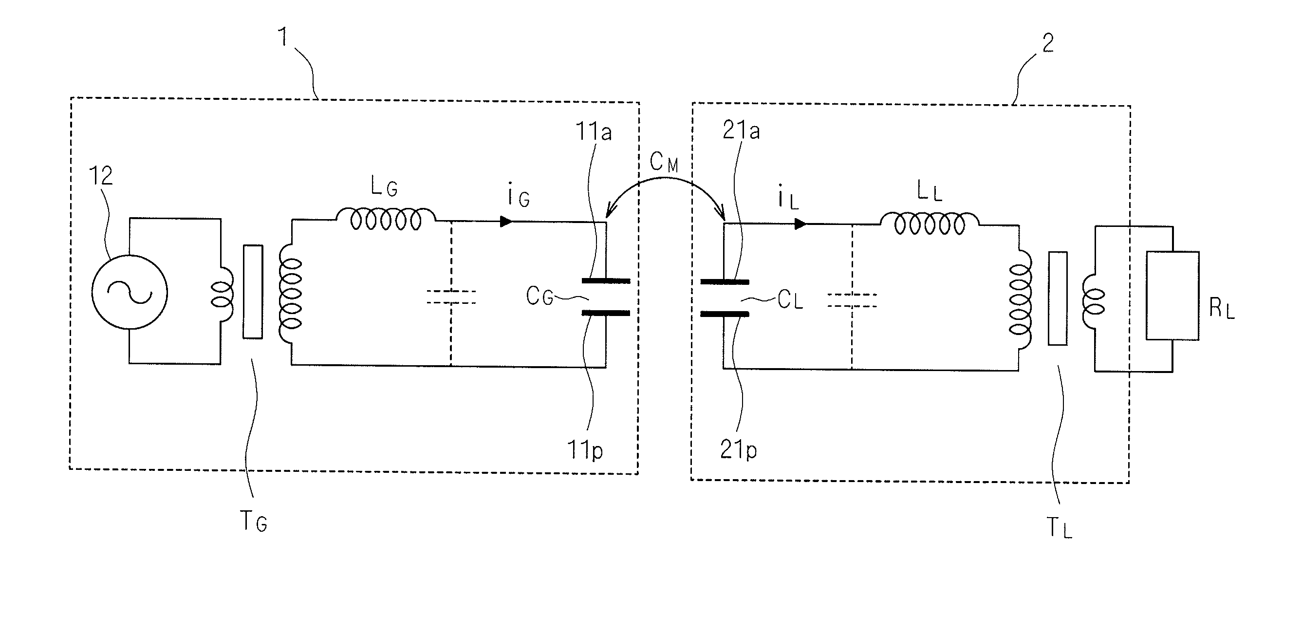
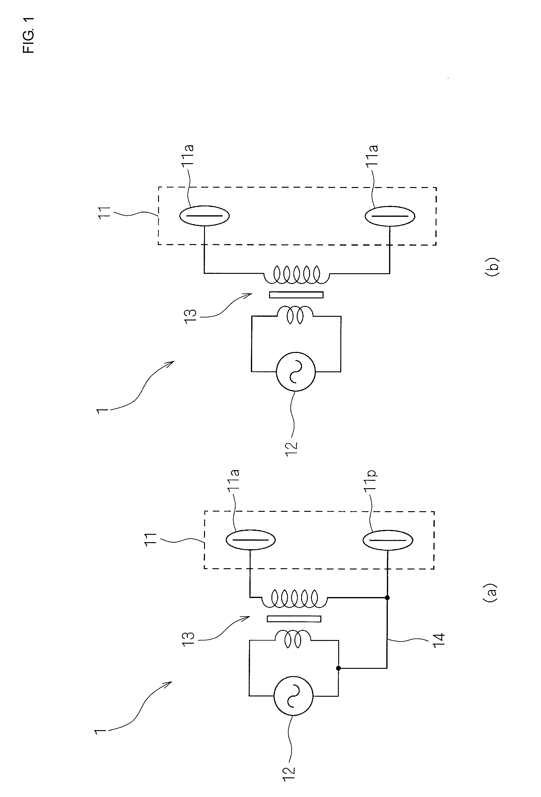
[0054]FIG. 1 is a circuit diagram schematically illustrating a configuration of a power transmission device according to embodiment 1 of the present invention. As illustrated in FIG. 1(a), a power transmission device 1 according to embodiment 1 at least includes a high-frequency generator circuit (power supply circuit) 12, a step up transformer 13, and first coupling electrodes 11 composed of a first active electrode 11a and a first passive electrode 11p. In the circuit of FIG. 1(a), when a voltage is stepped up by the step up transformer 13, the first active electrode 11a is at a high-voltage and the first passive electrode lip is at a low voltage.

[0055]As illustrated in FIG. 1(b), a ground wire 14 illustrated in FIG. 1(a) is not necessarily required. In the case where a voltage is stepped up by the step up transformer 13 without the ground wire 14 being provided, the first coupling electrodes 11 are both at a high-voltage and this is equivalent to a plurality of first active elect...

embodiment 2

[0088]Since the configuration of a power transmission system that employs a power transmission device according to embodiment 2 of the present invention is the same as that of embodiment 1, the same symbols will be used and therefore detailed description of the configuration will not be given. Embodiment 2 differs from embodiment 1 in that, in the power transmission state 404, in the case where it is determined that some abnormality has occurred, the power transmission device 1 is transitioned to the second standby state 405 and in the case where it is determined that charging has been completed, the power transmission device 1 is transitioned to a new third standby state.

[0089]FIG. 7 is a schematic diagram illustrating state transitions of the power transmission device 1 according to embodiment 2 of the present invention. As illustrated in FIG. 7, the power transmission device 1 is activated by for example being plugged into a wall socket or being connected to an A / C adapter (activ...

embodiment 3

[0107]Since the configuration of a power transmission system that employs a power transmission device according to embodiment 3 of the present invention is the same as that of embodiments 1 and 2, the same symbols are used and therefore detailed description of the configuration will not be given. Embodiment 3 differs from embodiments 1 and 2 in that the power transmission device 1 and the power reception device 2 communicate with each other and as a result power is transmitted at an operation frequency that is appropriate for the power reception device 2.

[0108]FIG. 9 is a flowchart illustrating a processing procedure of the control unit 102 of the power transmission device 1 according to embodiment 3 of the present invention. In FIG. 9, since the processing of step S601 and step S602 is the same as that in embodiment 1, detailed description thereof is omitted. Here, it is preferable that the high impedance value that is instructed to be set in step S602 be higher than in embodiments...


PUM


Abstract

Power transmission device that causes a power supply circuit to supply a first voltage to a first active electrode when power transmission is performed, causes the power supply circuit to supply a second voltage that is lower than the first voltage to the first active electrode and causes power reception device detection means to perform frequency sweeping at a first time interval until the power reception device is mounted, or causes the power supply circuit to supply a third voltage that is lower than the first voltage to the first active electrode and causes the power reception device detection means to perform frequency sweeping at a second time interval that is longer than the first time interval until the power reception device is removed.

Description

CROSS REFERENCE TO RELATED APPLICATIONS[0001]The present application is a continuation of PCT / JP2012 / 075364 filed Oct. 1, 2012, which claims priority to Japanese Patent Application No. 2011-256808, filed Nov. 24, 2011, the entire contents of each of which are incorporated herein by reference.FIELD OF THE INVENTION[0002]The present invention relates to a power transmission device and a power transmission control method for transmitting power without a physical connection by using electric field coupling. In particular, the present invention relates to a power transmission device and a power transmission control method that improve safety and reduce power consumption.BACKGROUND OF THE INVENTION[0003]In recent years, numerous electronic appliances that transmit power in a non-contact manner have been developed. In order to transmit power to an electronic appliance in a non-contact manner, a power transmission system is often adopted that employs a magnetic field coupling scheme in whic...

Claims


Application Information

Patent Timeline
IPC IPC(8): H02J7/00
CPCH02J7/00H02J5/005H02J7/00712H02J50/005H02J50/80H02J7/025H02J50/05H02J50/90
Inventor GOMA, SINJIICHIKAWA, KEIICHISUESADA, TSUYOSHI
Owner MURATA MFG CO LTD
Why Eureka
Try Eureka