Apparatus and Method for Branch Instruction Bonding

a branch instruction and bonding technology, applied in the field of computer architectures, can solve problems such as aggravated problems, escalating hardware costs, and reducing the benefits of building wider processors

Active Publication Date: 2014-09-11
MIPS TECH INC
View PDF3 Cites 2 Cited by
  • Summary
  • Abstract
  • Description
  • Claims
  • Application Information

AI Technical Summary

Problems solved by technology

Unfortunately, such superscalar designs require escalating hardware costs that dilute the benefits of building wider processors.
The problem is aggravated in speculative (typically out-of-order) processors that operate by dispatching more instructions per cycle than can be sustainably graduated.
This is a significant problem in many microprocessors, but the problem is particularly acute in synthesized processors, where the frequency loss of building a wider machine can rival the throughput gain of doing so.
Since frequency loss affects all programs and throughput gain only affects some, there is greater likelihood of an overall performance loss (because performance=throughput*frequency).
This strategy works fine in a power-unconstrained industry, but the extra power of a 4 channel versus a 3 channel processor can be intolerable in power-sensitive markets.
It is well known that increasing dispatch width (i.e., degree of superscalarity of a processor) causes quadratic increases in register renamer complexity and area.

Method used


Image

  • Apparatus and Method for Branch Instruction Bonding
  • Apparatus and Method for Branch Instruction Bonding

Examples


Embodiment Construction

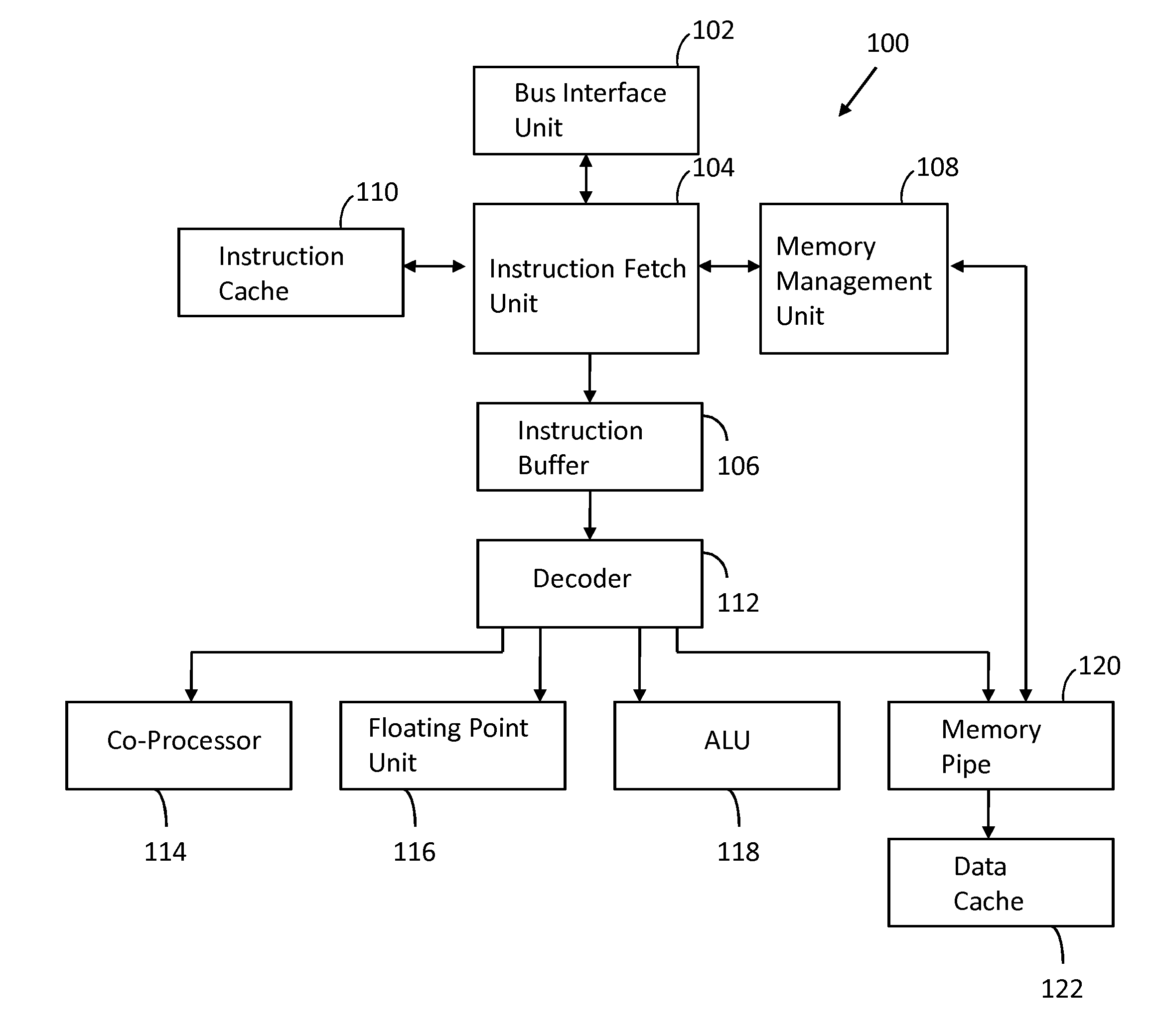
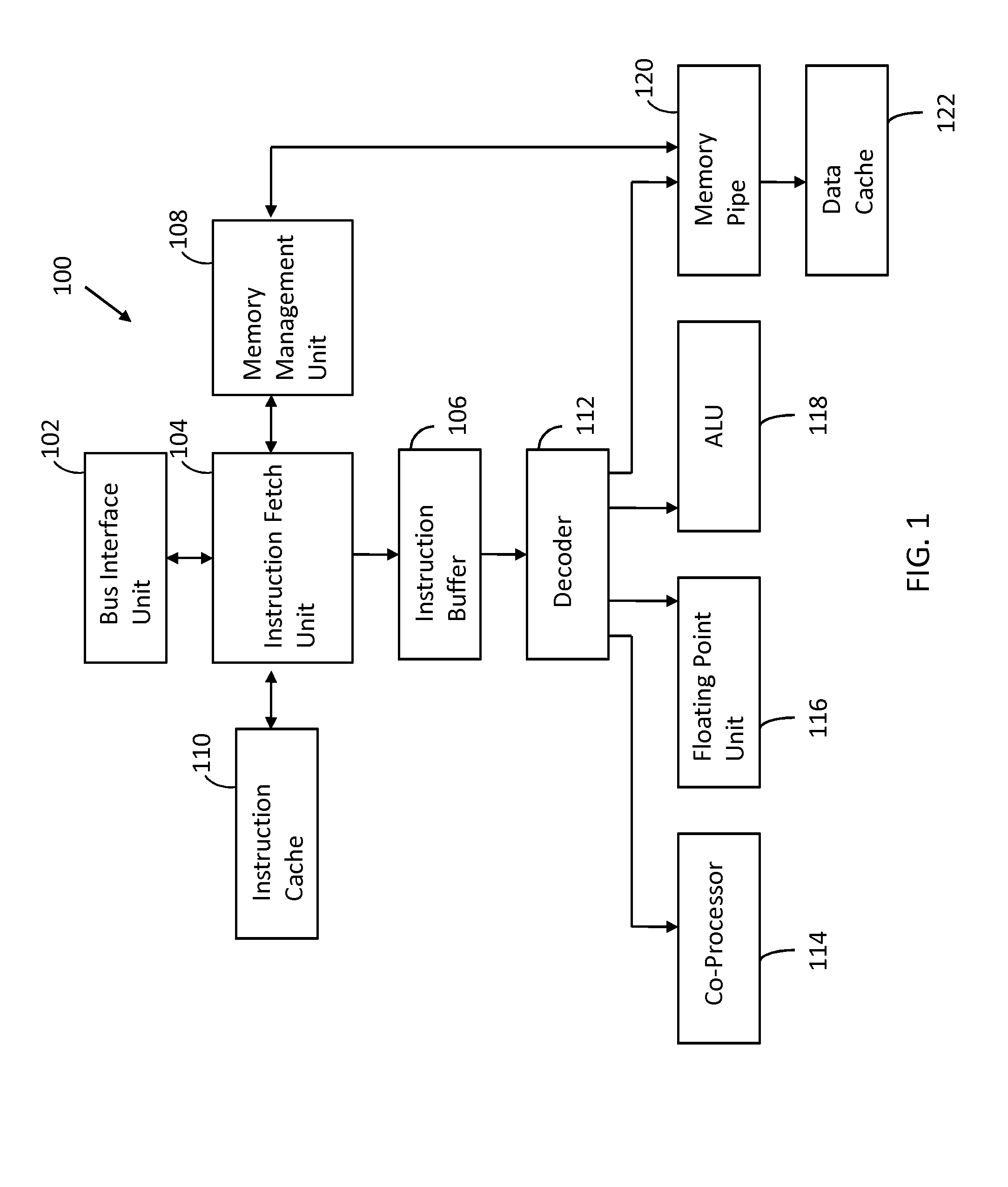
[0010]FIG. 1 illustrates a processor 100 configured in accordance with an embodiment of the invention. The processor 100 implements branch instruction bonding operations described herein. In particular, the processor bonds a branch instruction followed by an architectural delay slot (e.g., a no-operation instruction) into a single entity. As discussed below, this increases dispatch bandwidth at minimal cost.

[0011]The processor 100 includes a bus interface unit 102 connected to an instruction fetch unit 104. The instruction fetch unit 104 retrieves instructions from an instruction cache 110. The instruction fetch unit 104 is configured to identify branch instruction bonding opportunities. When such an opportunity exists, a branch instruction is bonded with a delay slot to form a single entity, which is written to the instruction buffer 106.

[0012]The memory management unit 108 provides virtual address to physical address translations for the instruction fetch unit 104. The memory mana...


PUM


Abstract

A processor is configured to identify a branch instruction immediately followed by an architectural delay slot. A single bonded instruction comprising the branch instruction immediately followed by the architectural delay slot is created. The single bonded instruction is loaded into an instruction buffer.

Description

FIELD OF THE INVENTION[0001]This invention relates generally to computer architectures. More particularly, this invention relates to processor architectures with branch instruction bonding.BACKGROUND OF THE INVENTION[0002]Superscalar processors dispatch more than one instruction per cycle to improve performance. Unfortunately, such superscalar designs require escalating hardware costs that dilute the benefits of building wider processors. The problem is aggravated in speculative (typically out-of-order) processors that operate by dispatching more instructions per cycle than can be sustainably graduated. The problem is further exacerbated by Reduced Instruction Set Computer (RISC) instruction sets, which have very simple instructions but consequently require even wider machines to compete with corresponding Complex Instruction Set Computer (CISC) machines.[0003]This is a significant problem in many microprocessors, but the problem is particularly acute in synthesized processors, wher...

Claims


Application Information

Patent Timeline
Patent Type & Authority Applications(United States)
IPC IPC(8): G06F9/30
CPCG06F9/30058G06F9/3804
Inventor SUDHAKAR, RANGANATHANPOTA, PARTHIV
Owner MIPS TECH INC
Why Eureka
Try Eureka