Combined heat and power (CHP) system

a heat exchanger and heat exchanger technology, applied in the direction of heat exchanger fastening, machines/engines, light and heating apparatus, etc., can solve the problems of reduced heat exchanger efficiency, increased exhaust of small particles by exhaust, contamination of filters and catalysts, etc., to achieve high reliability and efficiency, less prone to contamination, and easy maintenance

Inactive Publication Date: 2014-09-18
DEJATECH HLDG
View PDF7 Cites 4 Cited by
  • Summary
  • Abstract
  • Description
  • Claims
  • Application Information

AI Technical Summary

Benefits of technology

[0007]The present disclosure aims at an alternative CHP system. The present disclosure also aims at a CHP system which avoids or mitigates at least one or some of the problems of the known CHP systems as discussed in the introduction to this specification here above. The present disclosure furthermore or alternatively aims at a CHP system which is highly reliable and efficient, easy to maintain and / or less prone to contamination than the systems according to the prior art.

Problems solved by technology

In these CHP systems problems occur with the heat exchangers due to contamination carried in the exhaust gas from the turbine or engine.
Such contamination does get stuck inside the heat exchanger, especially in the flue duct or ducts, resulting in for example reduced efficiency of the heat exchanger, increased exhaust of small particles by the exhaust and contamination of for example filters and catalysts.
These known heat exchangers cannot be cleaned properly, which means that the heat exchangers have to be replaced relatively regularly, which is costly and time consuming.
Moreover, this reduces the environmental advantages that are strived for by a CHP.
Due to the straight pipes made of stainless steel, contamination by small particles and for example oil may be less of a problem then in cast aluminium heat exchangers, but such heat exchanger does not allow for cleaning in an easy manner either, without having to dismantle most of the heat exchanger.
Moreover, such CHP and especially the construction of the heat exchanger is very costly due to inter alia the metal used, and the necessity of welding all pipes and other parts together, water and gas tight.

Method used


Image

  • Combined heat and power (CHP) system
  • Combined heat and power (CHP) system
  • Combined heat and power (CHP) system

Examples


Embodiment Construction

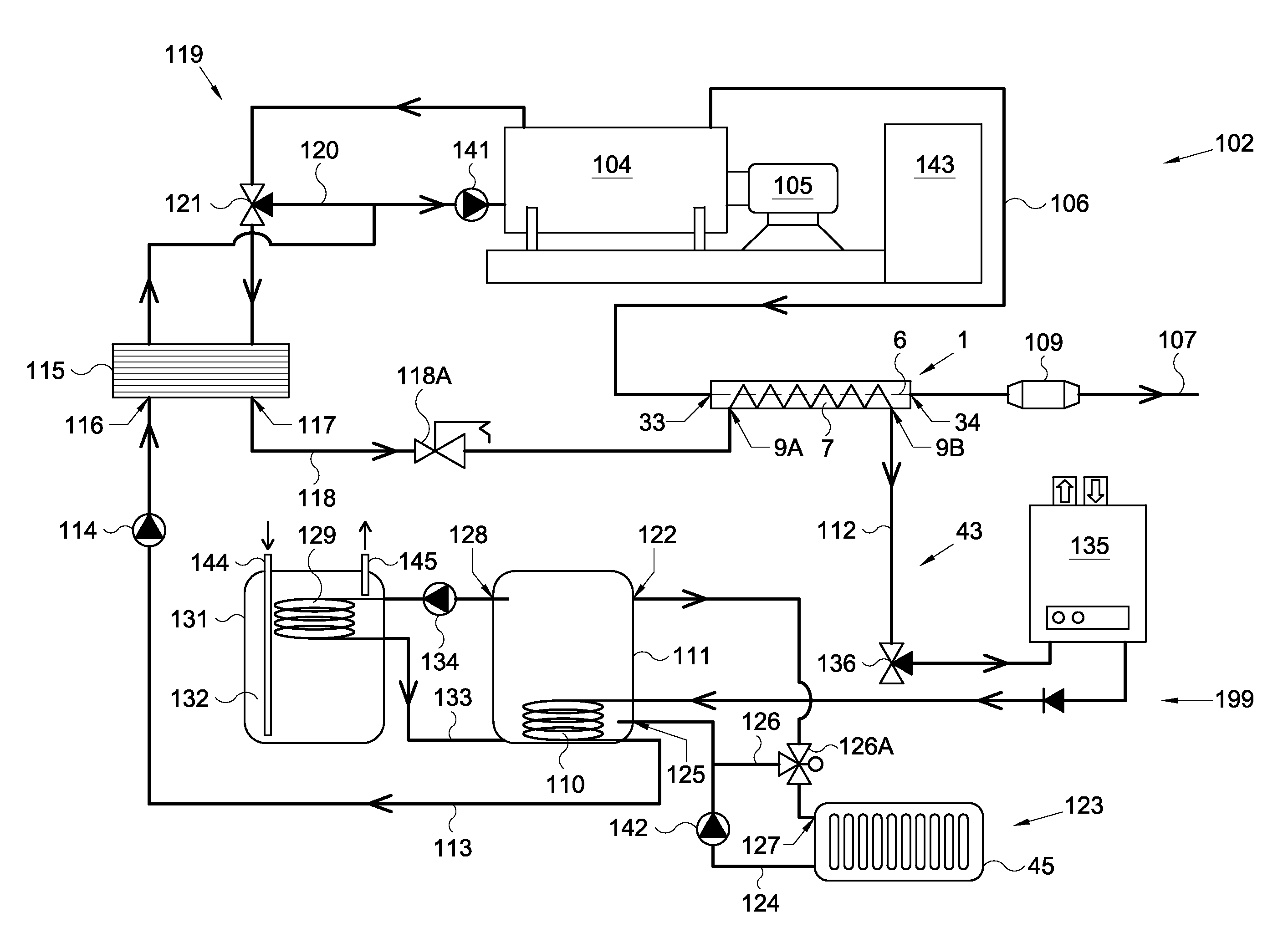
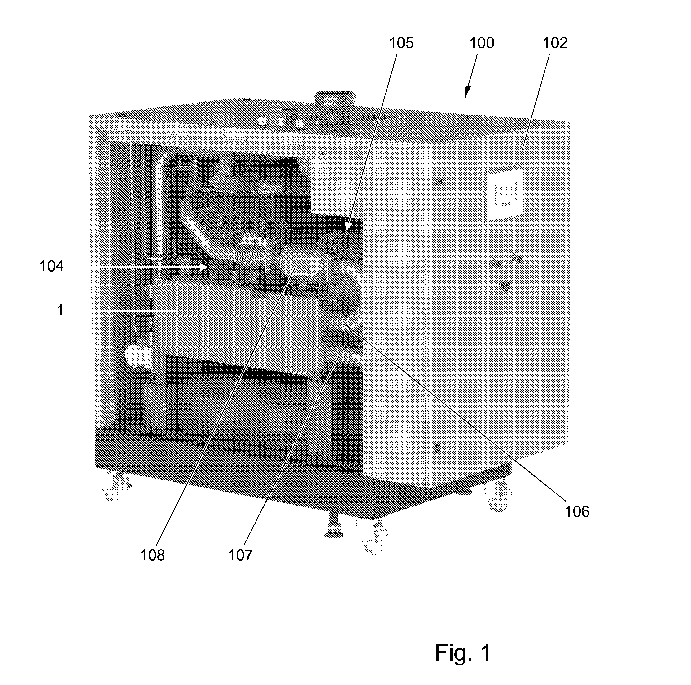
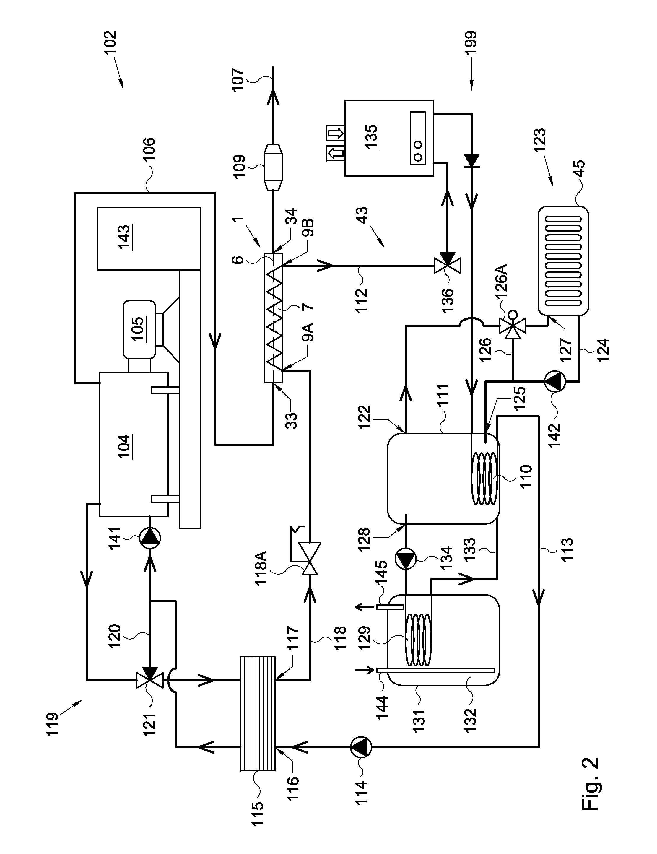
[0032]In this description different embodiments of a CHP system and parts thereof are disclosed and described. Moreover, in this description different embodiments of heat exchangers and parts thereof for such CHP systems, as well as heating circuits equipped therewith are disclosed and described by way of example only. In these embodiments the same or similar parts have the same or similar reference signs. Combinations of parts of the embodiments shown are also considered to have been disclosed herein. In this description a heat exchanger as to be understood as an exchanger for exchanging heat between heated flue gasses from an engine or turbine and possibly additionally a burner and water flowing through one or more water channels within said heat exchanger. Such CHP systems are especially, but not exclusively suitable in domestic and commercial heating systems such as for sanitary (tap) water and central heating systems, such as for space heating and / or tap water heating systems.

[...


PUM


Abstract

Combined Heat and Power (CHP) system, comprising an engine or turbine, a generator and a heat exchanger, wherein the heat exchanger has at least one flue duct in fluid communication with an exhaust of the engine or turbine and at least one fluid duct, the heat exchanger arranged for exchange of heat between flue gasses flowing through the at least one flue duct and a fluid flowing through said at least one fluid duct, wherein the at least one flue duct is formed by at least extrusion.

Description

CROSS-REFERENCE TO RELATED APPLICATIONS[0001]This application claims priority under 35 U.S.C. §119 to Application NL 2010441, filed Mar. 12, 2013, which is hereby incorporated by reference in its entirety.FIELD OF THE INVENTION[0002]The invention relates to a combined heat and power (CHP) system. Such systems are known in the art and combine an engine or turbine with a generator for generator electricity and with a heat exchanger for generating heated fluid, especially water for for example industrial or household use. Such water can for example be used for space heating, for tap water or for generating industrial heat for use in for example industrial processes.BACKGROUND OF THE INVENTION[0003]CHP systems are known comprising a heat exchanger made by casting or moulding from for example light metal, such as aluminium or aluminium alloy, such as for example disclosed in EP1752647, which has a standard heat exchanger of a central heating system integrated with a Stirling motor. The h...

Claims


Application Information

Patent Timeline
Patent Type & Authority Applications(United States)
IPC IPC(8): F01N5/02
CPCF01N5/02F01K23/10F02C6/18F28F3/048F28F21/084F28D9/0081F28F2275/025F28D21/001F28F2255/16F05D2220/64Y02E20/14Y02E20/16F01K5/02
Inventor DECKERS, JAN HUBERTUSTHIJSSEN, PAULUS MATHIJS MARIA
Owner DEJATECH HLDG
Why Eureka
Try Eureka