
Method and system for vacuum control

a vacuum control and vacuum technology, applied in the direction of electric control, machines/engines, combustion engines, etc., can solve the problem of small but measurable penalty in pumping work

Active Publication Date: 2014-09-18
FORD GLOBAL TECH LLC
View PDF2 Cites 53 Cited by
  • Summary
  • Abstract
  • Description
  • Claims
  • Application Information

AI Technical Summary

Benefits of technology

The patent describes a method for optimizing engine fuel injection based on operating conditions. By adjusting the amount of fuel injected via direct injection and port injection, the method aims to improve engine pumping efficiency and meet vacuum demand. The method can be used in engines with both direct injection and port fuel injection, and can be adjusted based on engine vacuum demand. The technical effect of this method is improved engine performance and efficiency under various operating conditions.

Problems solved by technology

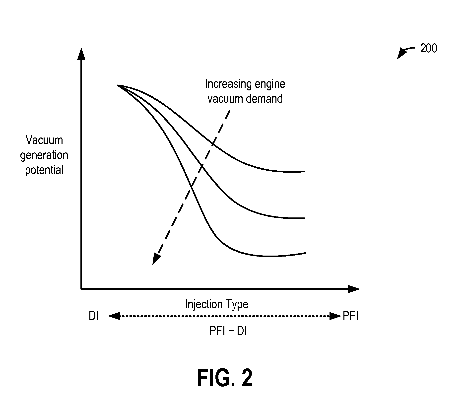
In contrast, at part-load conditions, direct injection results in a small but measurable penalty in pumping work.

Method used


Image

  • Method and system for vacuum control
  • Method and system for vacuum control
  • Method and system for vacuum control

Examples


Embodiment Construction

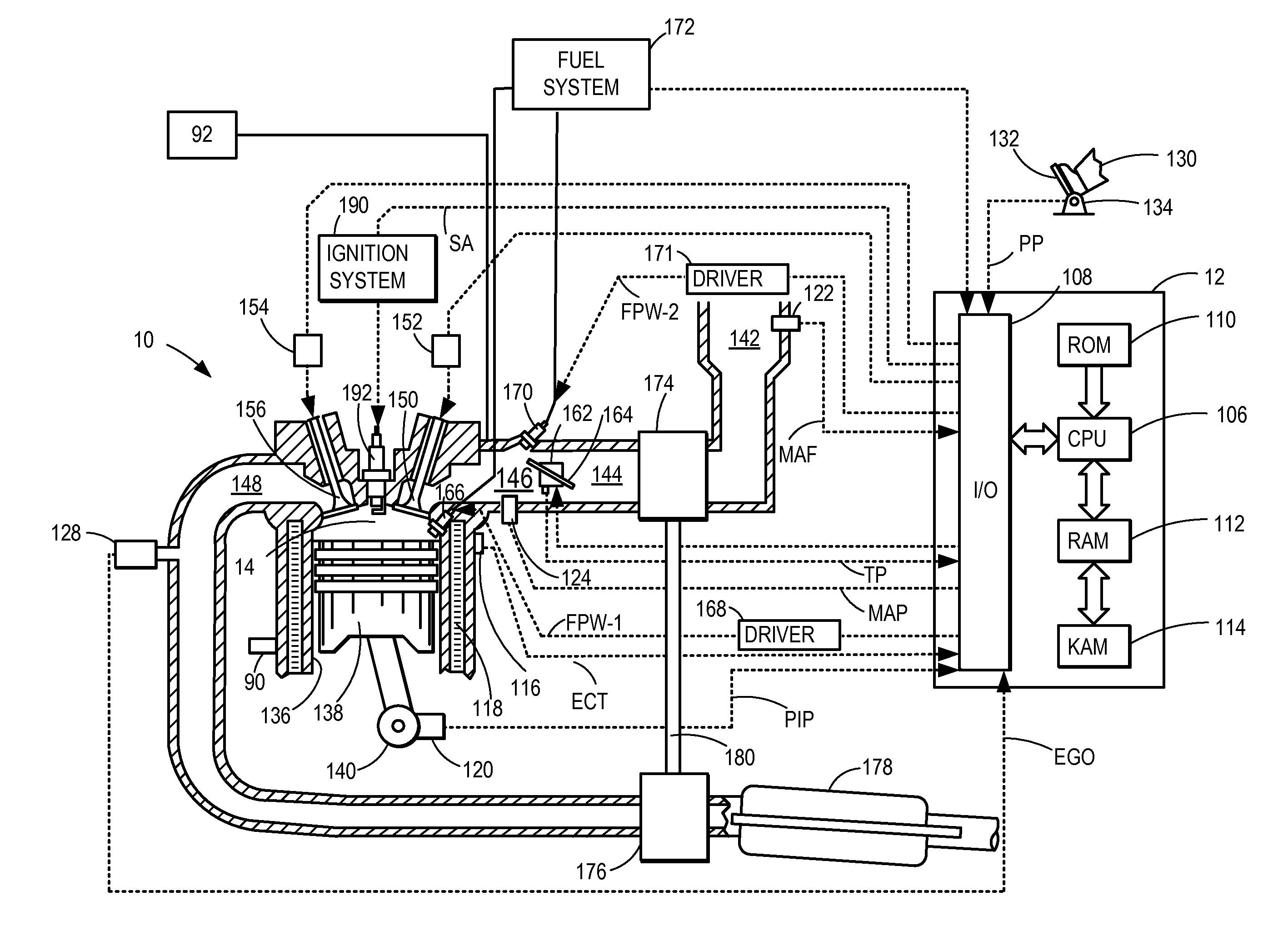
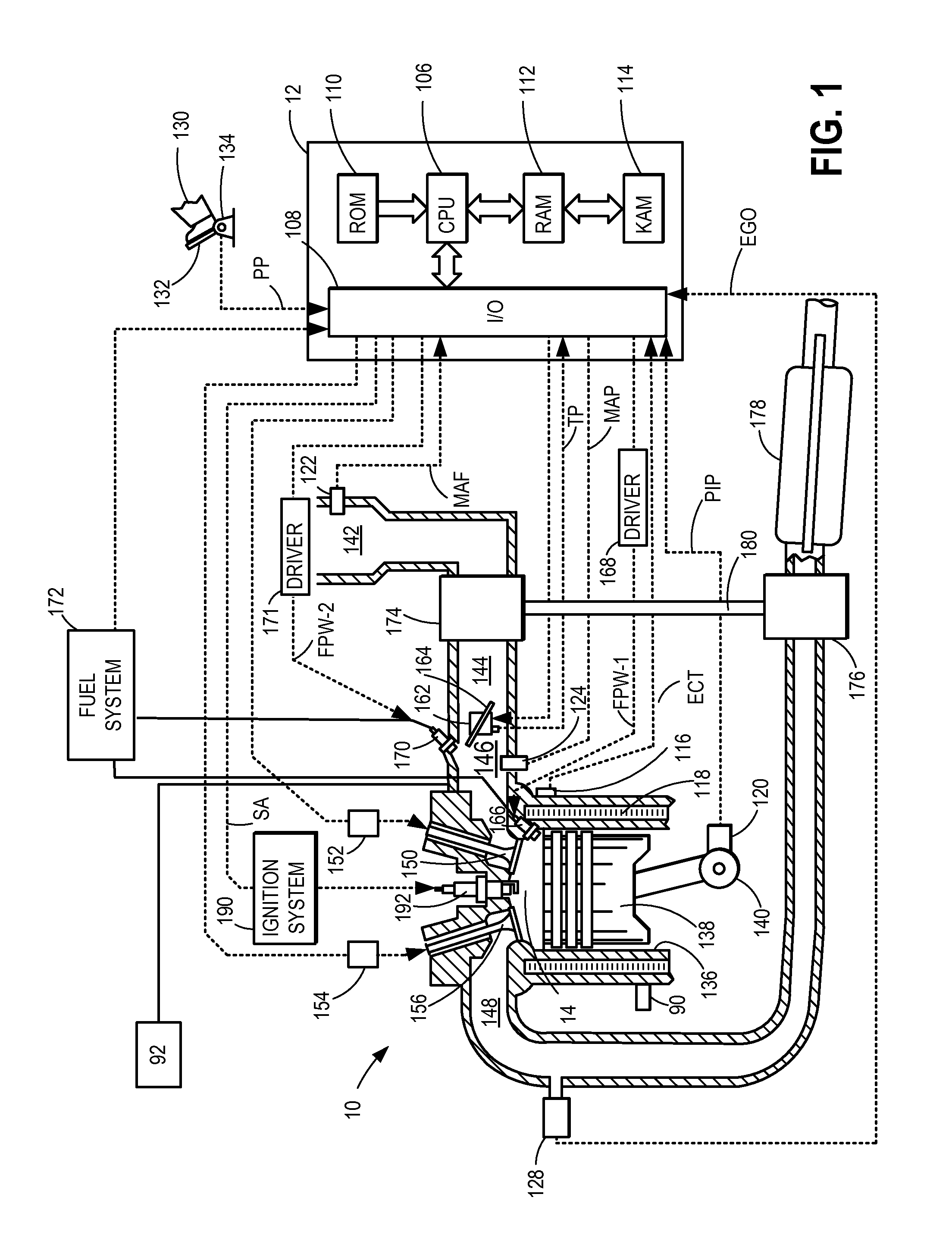
[0013]The following description relates to systems and methods for adjusting an engine fuel injection, such as in the engine system of FIG. 1, based on a vacuum requirement of the engine. As elaborated herein with reference to FIG. 3, an engine controller may adjust a fuel injection setting, specifically a proportion of fuel direct injected to the engine relative to fuel port injected into the engine, based on the engine's vacuum needs. The engine may need additional intake manifold vacuum for purging a fuel vapor canister, for crankcase ventilation, for providing vacuum assist to a vacuum consumer (such as a brake booster), etc. In response to the vacuum being generated at the intake manifold being less than the vacuum needed by the various vacuum consumers, the engine control system may shift to delivering a larger proportion of the fuel via direct injection while reducing the proportion of fuel delivered via port injection. The additional pumping work associated with the direct i...


PUM


Abstract

Methods and systems are provided for adjusting a fuel injection split between a direct injection and a port injection based on engine vacuum demand. When more intake manifold vacuum is required, relatively more direct injection is used to take advantage of the associated throttling for generating vacuum. The vacuum may then be used for canister purging, crankcase ventilation, or actuating an engine vacuum consumption device.

Description

FIELD[0001]The present application relates to methods and systems for controlling fuel injection in an engine system based on engine vacuum requirement.BACKGROUND AND SUMMARY[0002]Engines may be configured with direct fuel injectors that inject fuel directly into a combustion chamber (direct injection), and / or with port fuel injectors that inject fuel into an intake port (port fuel injection). The combined use of port injection and direct injection of a fuel allows the various benefits of each type of injection to be leveraged. For example, with port fuel injectors, the fuel is typically sprayed into the intake valves and ports. The injected fuel evaporates primarily due to contact with hot metal surfaces and / or due to backflow of hot exhaust gases during valve overlap. In contrast, with direct fuel injectors, fuel is sprayed directly into the combustion chamber and the injected fuel evaporates primarily due to smaller droplet size and thorough mixing. In addition, since there is li...

Claims


Application Information

Patent Timeline
Patent Type & Authority Applications(United States)
IPC IPC(8): F02B17/00
CPCF02B17/005F02D41/3094F02B23/104F02D13/0219F02D19/084F02D41/0002F02D2250/41Y02T10/30Y02T10/40
Inventor LEONE, THOMAS G.
Owner FORD GLOBAL TECH LLC
Learn More