
Small supercritical once-thru steam generator

a steam generator and supercritical technology, applied in the direction of ignition automatic control, application, borehole/well accessories, etc., can solve the problems of unsatisfactory results, difficult to split the steam/water mixture, and difficult to get an even mixture of steam/water in each downstream leg of the steam injector, so as to enhance the recovery

Active Publication Date: 2014-09-18
THE BABCOCK & WILCOX CO
View PDF6 Cites 17 Cited by
  • Summary
  • Abstract
  • Description
  • Claims
  • Application Information

AI Technical Summary

Benefits of technology

The present patent relates to apparatuses and methods for generating supercritical steam. The invention includes a supercritical once-through steam generator (OTSG) that includes a radiant section with a furnace coil and a convection section with a superheater. The OTSG is devoid of a steam separator and may produce single phase dry steam. The invention also includes a method for enhancing recovery from an underground hydrocarbon-containing reservoir by injecting supercritical steam into the reservoir through a plurality of injection wells. The invention also includes a method for retrofitting a steamflood boiler for supercritical steam injection by adding a superheater and replacing parts of the economizer and furnace coil with replacement parts. The technical effects of the invention include improved efficiency, reduced emissions, and improved recovery of hydrocarbons from underground reservoirs.

Problems solved by technology

Over the lifetime of a given well, the natural pressure of the hydrocarbon-containing reservoir will eventually fall, and the remaining hydrocarbons will be of high enough viscosity that conventional pumping systems will be unable to extract the hydrocarbons.
It can be difficult to split the steam / water mixture from current subcritical steamflood boilers evenly among the various injector wells and nozzles.
When there is a flow split in the piping system, it is very difficult to get an even mixture of steam / water in each of the downstream legs to the steam injectors.
This outcome is undesirable because it is important that each steam injection well receives a minimum “latent heat” for maximum recovery efficiency.
However, this increases equipment costs and leads to the liquid water portion of the steam / water mixture not being delivered, which significantly reduces overall system efficiency.

Method used


Image

  • Small supercritical once-thru steam generator
  • Small supercritical once-thru steam generator
  • Small supercritical once-thru steam generator

Examples


Embodiment Construction

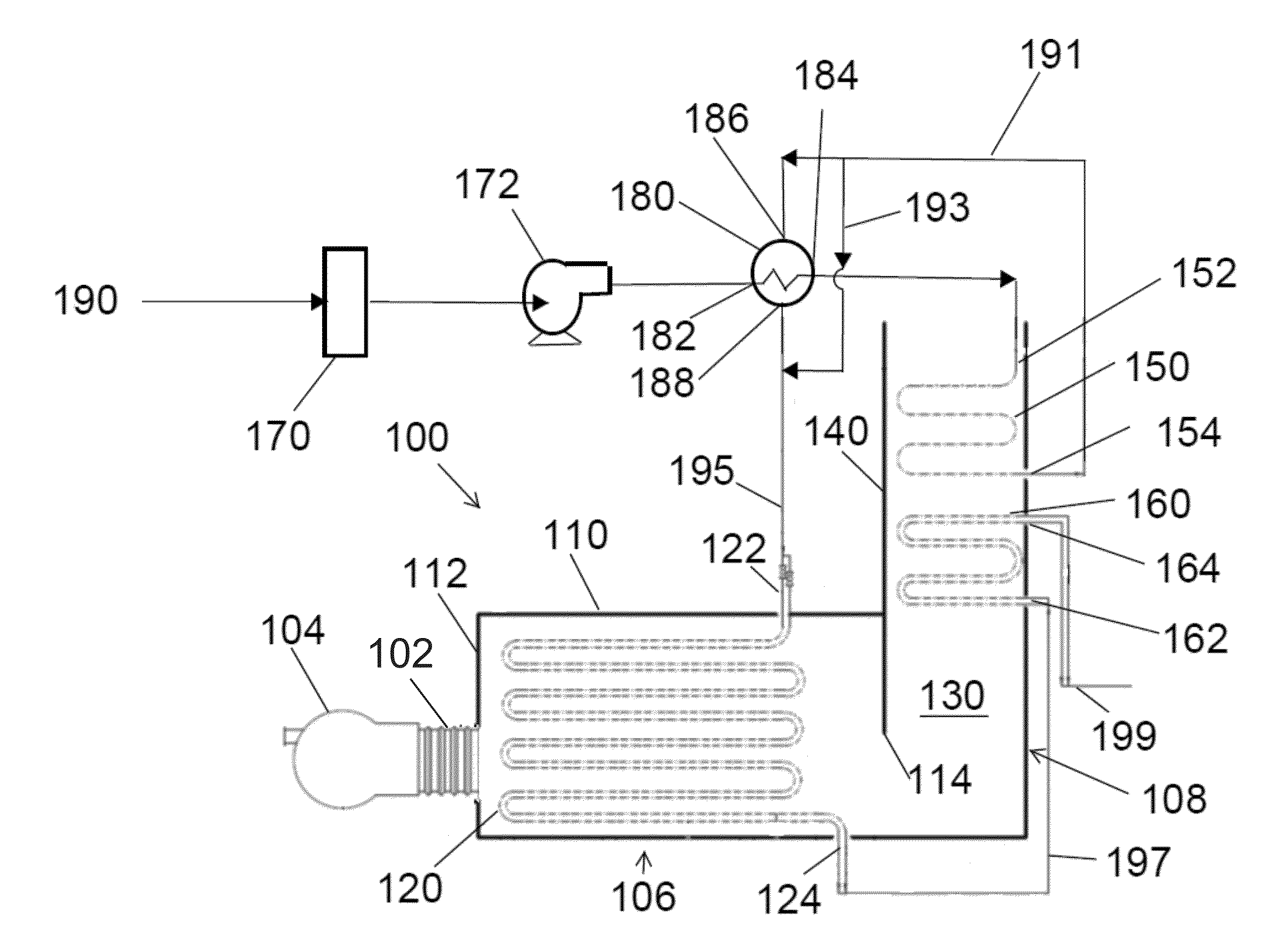
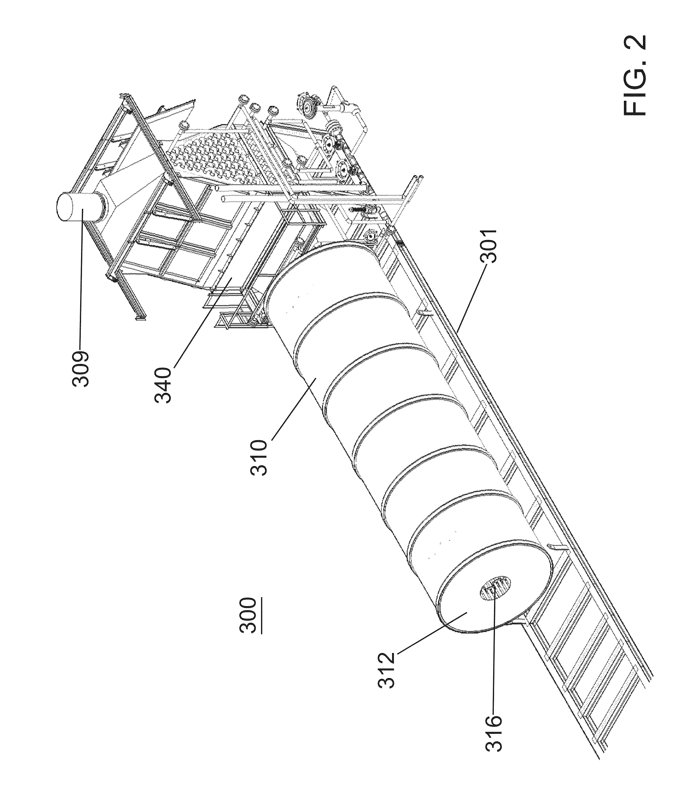
[0040]A more complete understanding of the processes and apparatuses disclosed herein can be obtained by reference to the accompanying drawings. These figures are merely schematic representations based on convenience and the ease of demonstrating the existing art and / or the present development, and are, therefore, not intended to indicate relative size and dimensions of the assemblies or components thereof.

[0041]Although specific terms are used in the following description for the sake of clarity, these terms are intended to refer only to the particular structure of the embodiments selected for illustration in the drawings, and are not intended to define or limit the scope of the disclosure. In the drawings and the following description below, it is to be understood that like numeric designations refer to components of like function.

[0042]The modifier “about” used in connection with a quantity is inclusive of the stated value and has the meaning dictated by the context (for example,...


PUM

PropertyMeasurementUnit
pressuresaaaaaaaaaa
pressuresaaaaaaaaaa
pressureaaaaaaaaaa

Abstract

A small supercritical once-through steam generator (OTSG) includes a radiant section with a furnace coil, and a convection section downstream of the radiant section that includes a superheater which is fluidically connected to the furnace coil. Optionally, the OTSG is devoid of a steam separator. An economizer can also be included downstream of the superheater. Supercritical steam can be generated using the OTSG, for use, among other things, in enhanced oil recovery applications.

Description

BACKGROUND[0001]The present disclosure relates generally to apparatuses, devices, and associated equipment used to produce supercritical steam. The supercritical steam may be used with advanced methods of enhancing oil recovery, among other processes.[0002]Nearly two-thirds of the world's energy demand is satisfied by oil and natural gas, including the vast majority of transportation fuel in developed countries. However, the demand for energy continues to increase. Concurrently, hydrocarbon (i.e., oil and gas) reservoirs located within the Earth's strata differ in the ease with which their hydrocarbons can be extracted. The reservoirs that are easiest to produce from are more quickly exhausted.[0003]Extraction of hydrocarbons (i.e., oil and gas) occurs in multiple stages. During the primary recovery stage, the natural underground pressure of the hydrocarbon-containing reservoir / formation and / or conventional pumping systems are used to extract low viscosity (i.e., pumpable) hydrocarb...

Claims


Application Information

Patent Timeline
Patent Type & Authority Applications(United States)
IPC IPC(8): F22B29/06E21B43/24F22G7/12F22D1/02F22G1/02
CPCF22B29/064E21B43/24F22G7/12F22G1/02F22D1/02F22B29/06Y10T29/49387
Inventor COSTANZO, MICHAEL A.BLOSS, JAMES S.
Owner THE BABCOCK & WILCOX CO
Learn More