Stress relief for array-based electronic devices

a technology of electronic devices and stress relief, applied in the field of electronic devices, can solve problems such as mechanical stress, reduced performance, partial or complete system failure, etc., and achieve the effect of reducing stress on components

Inactive Publication Date: 2014-09-18
COOLEDGE LIGHTING
View PDF9 Cites 63 Cited by
  • Summary
  • Abstract
  • Description
  • Claims
  • Application Information

AI Technical Summary

Benefits of technology

[0006]In accordance with certain embodiments, lighting systems are fabricated utilizing discrete lightsheets fabricated on flexible substrates that typically include conductive traces interconnecting large arrays of light-emitting elements (LEEs) and control elements, which govern or affect operation of the LEEs. Control elements may include one or more passive components, such as resistors, capacitors, inductors, or fuses, as well as active components, e.g., transistors and diodes. Advantageously, stress on components may be reduced by replacing a discrete component with a “distribu...

Problems solved by technology

One challenge for systems based on plastic substrates is the reduction of mechanical stress on the components mounted on the circuit board.
Mechanical stress may...

Method used


Image

  • Stress relief for array-based electronic devices
  • Stress relief for array-based electronic devices
  • Stress relief for array-based electronic devices

Examples


Embodiment Construction

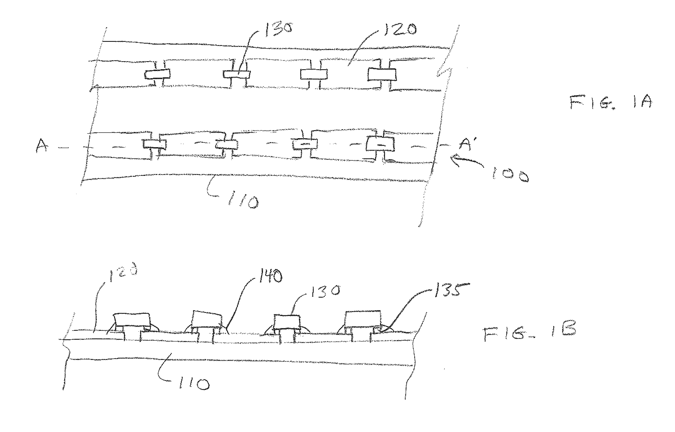
[0044]FIG. 1A is a plan view of a lightsheet 100, and FIG. 1B is a cross-sectional view of lightsheet 100 through cut-line A-A′. Lightsheet 100 includes or consists essentially of a substrate 110 over which are formed conductive traces 120. FIG. 1A shows one component 130 attached to conductive traces 120; however, more than one component 130 may be used in preferred embodiments. Each component 130 may include or consist essentially of an LEE or other active or passive component, such as a transistor, resistor, capacitor, inductor, diode, etc. In FIGS. 1A and 1B, component 130 has two contacts 135 that are electrically coupled to conductive traces 120 using an adhesive 140. In some embodiments, adhesive 140 includes or consists essentially of an anisotropic conductive adhesive (ACA); however, the method of electrically coupling contacts 135 to conductive traces 120 is not a limitation of the present invention. In some embodiments, adhesive 140 may also mechanically attach component ...


PUM


Abstract

In accordance with certain embodiments, an electric device includes a flexible substrate having first and second conductive traces on a first surface thereof and separated by a gap therebetween, an electronic component spanning the gap, and a stiffener configured to substantially prevent flexing of the substrate proximate the gap during flexing of the substrate.

Description

RELATED APPLICATION[0001]This application claims the benefit of and priority to U.S. Provisional Patent Application No. 61 / 788,980, filed Mar. 15, 2013, the entire disclosure of which is incorporated herein by reference.FIELD OF THE INVENTION[0002]In various embodiments, the present invention generally relates to electronic devices, and more specifically to array-based electronic devices.BACKGROUND[0003]Light sources such as light-emitting diodes (LEDs) are an attractive alternative to incandescent and fluorescent light bulbs in illumination devices due to their higher efficiency, smaller form factor, longer lifetime, and enhanced mechanical robustness. Such systems typically have multiple LEDs, and optionally other passive or active components, mounted on a printed circuit or wiring board. The printed circuit board may be fiberglass, such as FR4, or, for cases in which higher heat loads must be managed, a metal core printed circuit board (MCPCB). The cost of these systems must be r...

Claims


Application Information

Patent Timeline
IPC IPC(8): H01L33/62
CPCH01L33/62H01L2224/16225H01L2924/07811H01L25/0753H01L2924/00H01L33/38H01L25/13H01L33/483
Inventor TISCHLER, MICHAEL A.PALFREYMAN, PAULSCHICK, PHILIPPE M.
Owner COOLEDGE LIGHTING
Why Eureka
Try Eureka