
System and method for a programmable electric converter

a technology of programmable electric converters and converters, applied in the direction of dynamo-electric converter control, synchronous generators with multiple outputs, motor/generator/converter stoppers, etc., can solve the problems of limiting the usefulness of such a generator, and limiting the usefulness of electric motors

Active Publication Date: 2014-09-18
ACME PROD DEV
View PDF77 Cites 5 Cited by
  • Summary
  • Abstract
  • Description
  • Claims
  • Application Information

AI Technical Summary

Benefits of technology

The invention described in this patent has various benefits that can be realized in different embodiments. The technical effects of the patent cannot be fully represented in this summary, but it provides a summary of the benefits that can be gained from the invention.

Problems solved by technology

Prior art electro-magnetic machines suffer from a variety of limitations which have limited their usefulness somewhat.
For example, the frequency and voltage of a permanent magnet electro-magnetic machine operating as a generator may only be varied by varying the rotor speed, which limits the usefulness of such a generator in circumstances where the rotor rotation speed cannot be independently controlled.
Commutator-type motors do not operate well on high-frequency AC because the rapid changes of current are opposed by the inductance of the motor field.
For very slow prime mover speeds, it would be costly to build a generator with enough poles to provide a high AC frequency.
While belt drives were common as a way to increase speed of slow engines, in very large ratings (thousands of kilowatts) these were expensive, inefficient and unreliable.

Method used


Image

  • System and method for a programmable electric converter
  • System and method for a programmable electric converter
  • System and method for a programmable electric converter

Examples


Embodiment Construction

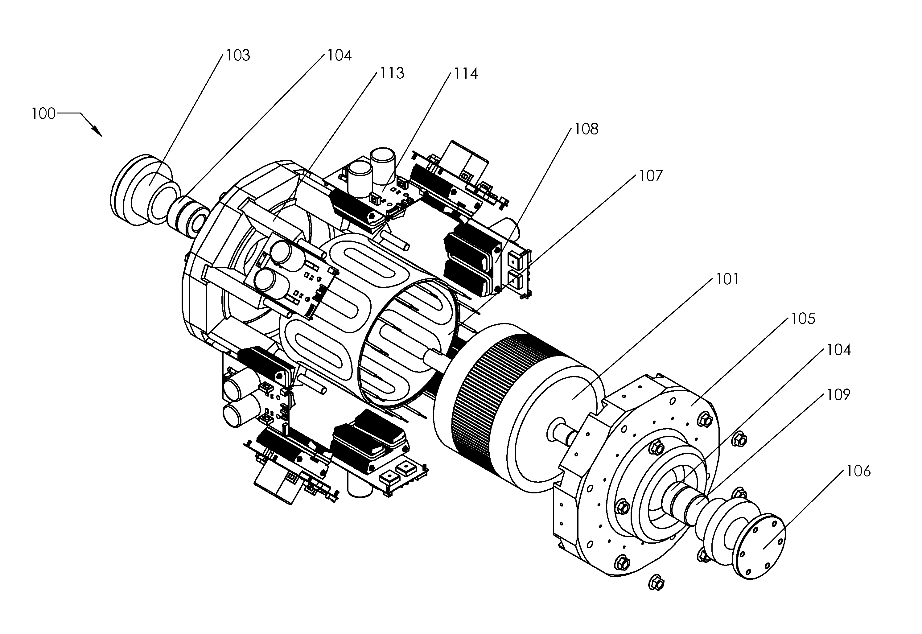
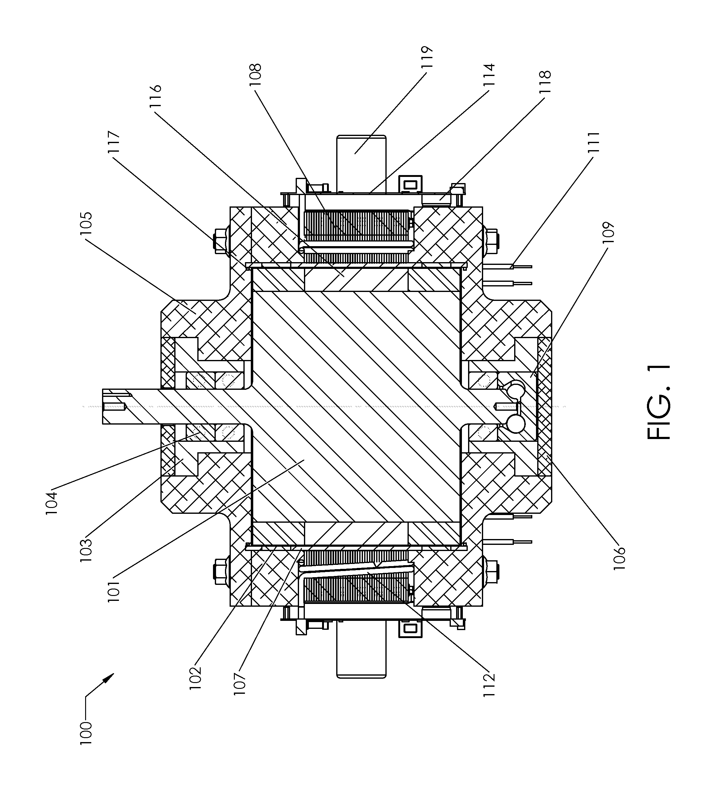
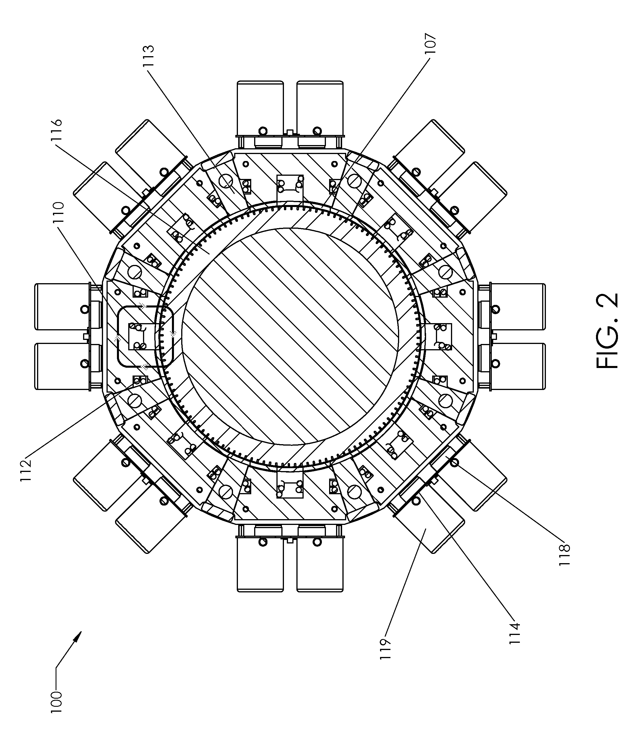
[0032]Referring to FIGS. 1-3 collectively, an embodiment of a programmable electric converter 100 is shown. In the embodiment shown, a rotor 101 having extrusions on either side thereof along an axis of rotation with one shaft extending thru an end plate 106, the rotor being rotatably secured in place via endplates 105 disposed on either side thereof having bearing assemblies (103, 104, 106, 109). Around a circumference of the rotor are disposed a plurality of C-core field coil cells 108 for inducing a magnetic field 110 in the rotor. An armature 107 is disposed between the rotor 101 and the field coil cells 108.

[0033]In some embodiments, the axis of rotation of the rotor 101 of the programmable electric converter 100 may be on a horizontal or vertical axis. In operation, the programmable electric converter 100 may use independently controlled field coils 108 to impress a temporary magnetic field 110 on a cylindrical rotor 101 spinning inside one or more armatures 107. These armatur...


PUM


Abstract

An electric converter is provided which uses independently controlled field coils to impress a temporary magnetic field on a rotor movable relative to one or more armatures. In some embodiments, the rotor of the programmable electric converter is rotatable with the axis of rotation being on a horizontal or vertical axis. In various embodiments, the electric converter disclosed herein may be adapted for use as a continuous power solution to provide power for a limited period of time in the event of a power outage by absorbing energy and storing it mechanically in the rotor. In some embodiments, the electric converter may be utilized as a generator. In some embodiments, both AC and DC could be simultaneously produced, where AC is generated in one armature coil and DC in another coil. In some embodiments, the programmable electric converter can operate as an AC to AC converter, AC to DC converter, DC to AC converter, or DC to DC converter. In some embodiments, the electro-magnetic converter may be utilized to provide electro-magnetic propulsion to provide precise acceleration profiles and capture regenerative braking energy.

Description

CROSS-REFERENCE TO RELATED APPLICATIONS[0001]This patent application claims priority to U.S. Provisional Patent Application Ser. No. 61 / 617,018, filed Mar. 28, 2012.BACKGROUND[0002]1. Technical Field[0003]This invention relates in general to the field of electric converters, and more particularly, but not by way of limitation to a programmable electric converter.[0004]2. Background[0005]Electro-magnetic machines have been used as generators or as motors or both simultaneously. The operation of the electro-magnetic machine is determined by the type of energy used to drive the machine and the type of energy which is obtained from the operation of the machine. For example, if electrical energy is delivered to the machine and mechanical energy is removed from the machine, then the machine will operate as a motor. Likewise, if mechanical energy is delivered to the machine and electrical energy is removed from the machine, then the machine will act as a generator. In some cases the machin...

Claims


Application Information

Patent Timeline
Patent Type & Authority Applications(United States)
IPC IPC(8): H02P11/04
CPCH02P11/04H02K1/00H02K19/106H02K21/046H02K21/48H02K47/00H02K2213/09H02K2213/12H02K11/33H02K99/00H02K99/10H02K99/20
Inventor LEE, RANDAL A.
Owner ACME PROD DEV
Learn More