Antenna having split directors and antenna array comprising same

a technology of antenna array and split director, which is applied in the field of antenna array, can solve the problems of difficult to obtain the desired combined pattern with suitable precision, the radiation pattern provided by the classic yagi-uda antenna and its variants, and the inability to fully suit all applications,

Inactive Publication Date: 2014-09-18
SIERRA WIRELESS
View PDF6 Cites 150 Cited by
  • Summary
  • Abstract
  • Description
  • Claims
  • Application Information

AI Technical Summary

Benefits of technology

[0008]In accordance with an aspect of the present invention, there is provided an antenna array comprising two or more antennas, at least one of said two or more antennas comprising: a first driven element disposed on a first side of a reference plane and a second driven element spaced apart from the first driven element and disposed on a second side of the reference plane opposite the first side; a first passive element disposed within near-field distance of the first driven element, the first passive element disposed on the first side of the reference plane; and a second passive element disposed within near-field distance of the second driven element, the second passive element spaced apart from the first passive element and disposed on the second side of the reference plane.

Problems solved by technology

However, the characteristic radiation pattern provided by the classic Yagi-Uda antenna and its variants may not be completely suitable for all applications.
However, with standard antenna designs, such as the Yagi-Uda antenna, the desired combined pattern can be difficult to obtain with suitable precision.
In addition, packing more than a few antennas into a small space may be problematic both spatially and due to potential mutual coupling and interference problems.

Method used


Image

  • Antenna having split directors and antenna array comprising same
  • Antenna having split directors and antenna array comprising same
  • Antenna having split directors and antenna array comprising same

Examples


example 1

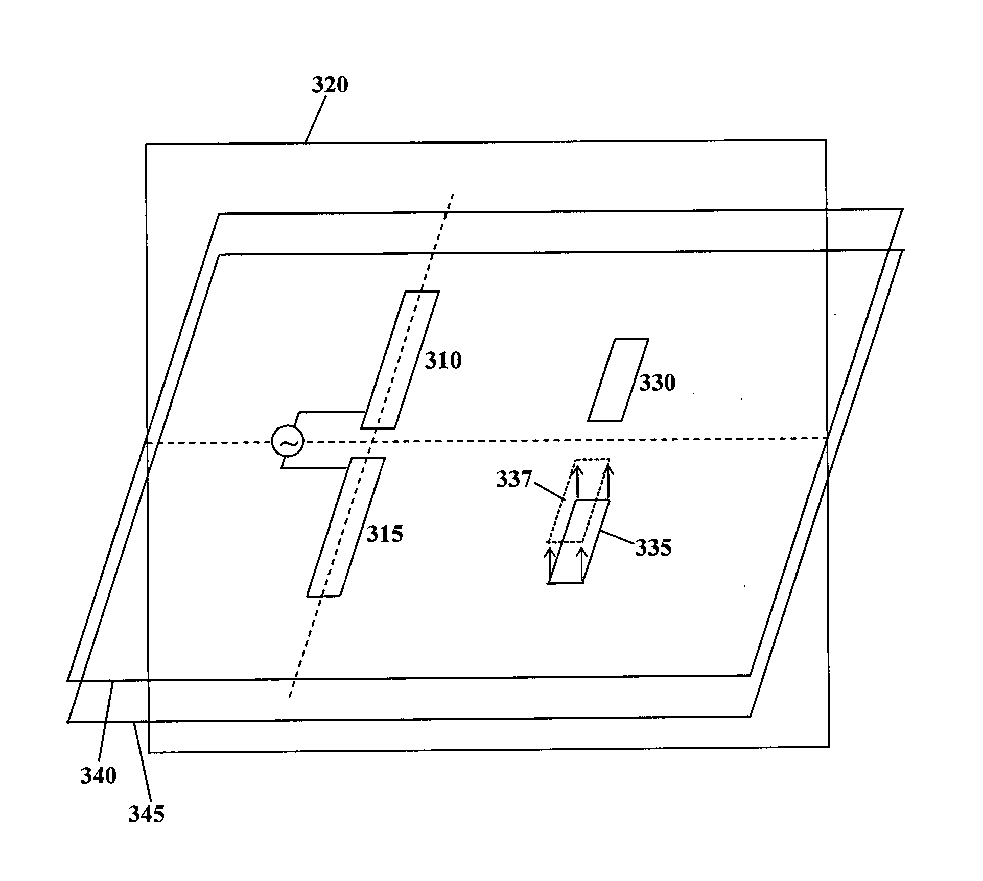
[0072]FIGS. 5a and 5b illustrate front and back views of a printed circuit board comprising an antenna 500 provided in accordance with an embodiment of the present technology. The antenna comprises a pair of driven elements 510, 515, and a pair of passive elements 530, 535. The antenna may be coupled to a transmission line. Further conductive elements 540 and 545 are provided on the back side of the printed circuit board. Element 540 is a printed wire reflector. Element 545 is a free floating patch which may offer shunt capacitance for impedance matching purposes. Together with a shunt inductor which may be formed by part of the reflector 540, a distributed shunt resonator may be provided, for example to improve antenna bandwidth. The antenna 500 defines a substantially directional radiation pattern within the plane of the printed circuit board. A pair of antennas 500, oriented in opposite directions and placed proximate to each other may define an antenna array, in which the direct...


PUM


Abstract

An antenna is provided comprising a pair of driven elements and a pair of passive elements. The driven elements are disposed on opposite sides of a reference plane, and the passive elements are also disposed on opposite sides of the reference plane. One or both passive elements may be provided in a different plane than the driven elements. By varying placement of the passive elements the antenna radiation pattern can be altered. An antenna array is also provided, comprising two or more oppositely directed directional antennas at least one of which is as described above. The passive elements of the antennas can be adjusted for a desired coverage pattern of the array, such as an azimuthal omnidirectional pattern, for example through simulation. The antenna or array may be embodied on a printed circuit board.

Description

FIELD OF THE TECHNOLOGY[0001]The present technology pertains in general to antennas and in particular to antennas and antenna arrays having both active and passive elements.BACKGROUND[0002]Antennas are widely used in the field of communications. Various designs, particularly for portable electronic devices, involve antennas provided as circuit traces on a printed circuit board (PCB).[0003]A well-known antenna is the Yagi-Uda antenna, which includes a driven dipole and a series of reflectors and directors arranged in parallel with the dipole. A reflector is a single body which is longer than the dipole, while the directors are single bodies which are shorter than the dipole. Reflectors and directors and dipoles are typically symmetric about a common axis. The Yagi-Uda antenna is typically used to provide a directional radio signal. Specifically, the Yagi-Uda antenna can be made to have higher gain in one direction relative to a standard dipole antenna or isotropic radiator, thus exhi...

Claims


Application Information

Patent Timeline
Patent Type & Authority Applications(United States)
IPC IPC(8): H01Q9/20H01Q5/00
CPCH01Q5/0065H01Q9/20H01Q9/065H01Q9/285H01Q19/30H01Q25/005
Inventor YEN, CHIH-CHUAN
Owner SIERRA WIRELESS
Why Eureka
Try Eureka