Multimotor variable frequency overload

a multi-variable frequency, overload technology, applied in the direction of emergency protective arrangements, instruments, lighting and heating apparatus, etc., can solve the problems of increasing the cost of the motor, without providing any advanced warning, etc., and achieve the effect of reducing the cooling

Active Publication Date: 2014-09-18
ROCKWELL AUTOMATION TECH
View PDF11 Cites 5 Cited by
  • Summary
  • Abstract
  • Description
  • Claims
  • Application Information

AI Technical Summary

Benefits of technology

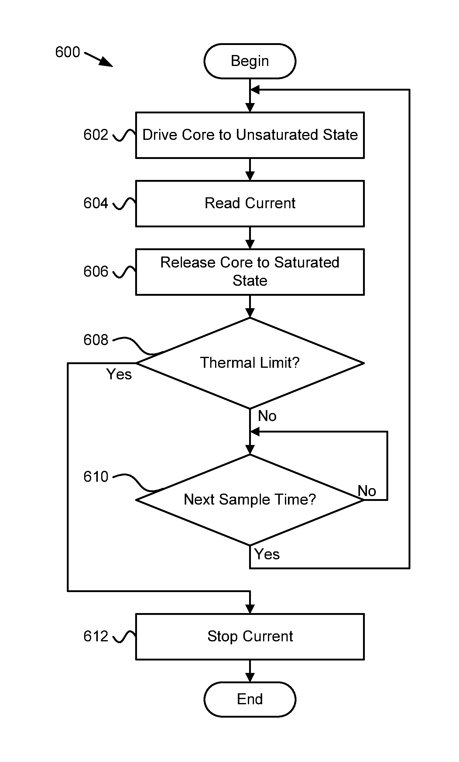
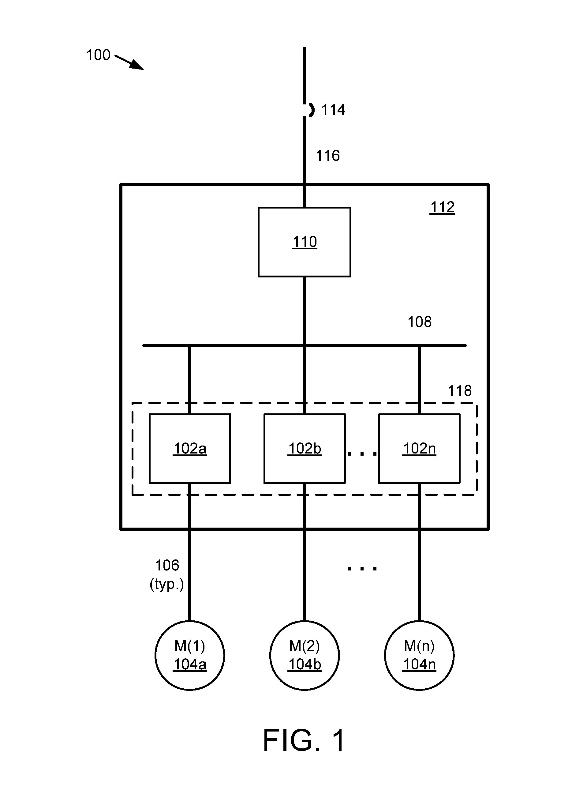
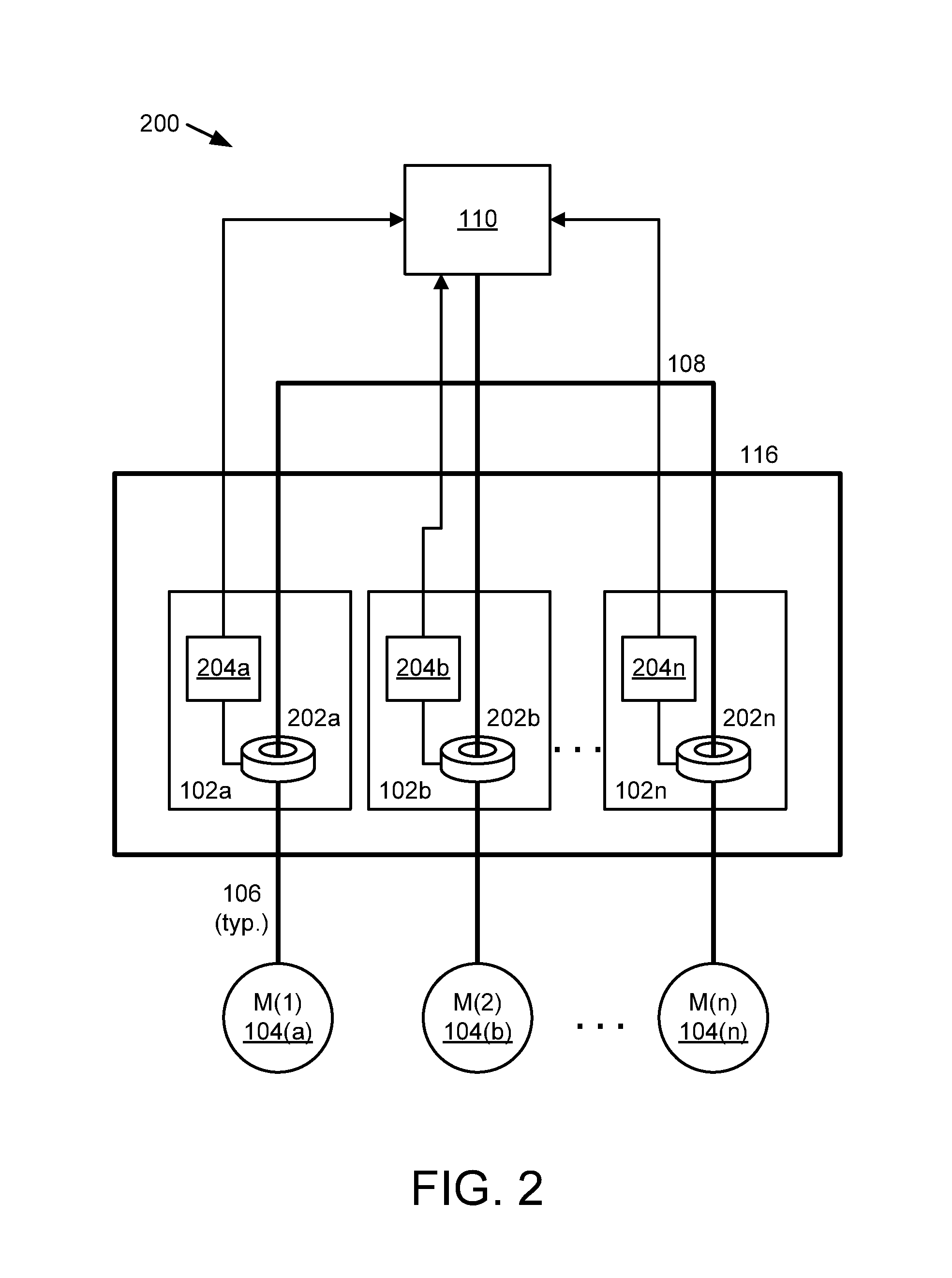
[0009]In one embodiment, the one or more current sensors for the motor overload protecting the protected motor include a current sensor for each line voltage phase providing power to the protected motor. In another embodiment, the motor trip module includes a speed adjustment module that adjusts the thermal limit as a function of motor speed. In a further embodiment, the speed adjustment module adjusts the thermal limit as a function of motor speed by accounting for a reduced cooling effect when the protected motor operates at a speed below a rated full speed. In another embodiment, each motor trip module stops flow to the protected motor by adjusting power to a coil of a contactor of a motor starter to open the contactor or commands a variable frequency drive powering the two or more motors to a state where power to the two or more motors is interrupted. In another embodiment, the two or more motors are of different sizes. In another embodiment, the apparatus includes an overload module that displays a reading of how close the protected motor is to reaching the thermal limit.

Problems solved by technology

Many motor overloads are mechanical in nature and often trip without providing any advanced warning.
Some AC electric motors include a motor overload, but inclusion of a motor overload typically increases the cost of a motor.

Method used


Image

  • Multimotor variable frequency overload
  • Multimotor variable frequency overload
  • Multimotor variable frequency overload

Examples


Embodiment Construction

[0021]Reference throughout this specification to “one embodiment,”“an embodiment,” or similar language means that a particular feature, structure, or characteristic described in connection with the embodiment is included in at least one embodiment. Thus, appearances of the phrases “in one embodiment,”“in an embodiment,” and similar language throughout this specification may, but do not necessarily, all refer to the same embodiment, but mean “one or more but not all embodiments” unless expressly specified otherwise. The terms “including,”“comprising,”“having,” and variations thereof mean “including but not limited to” unless expressly specified otherwise. An enumerated listing of items does not imply that any or all of the items are mutually exclusive and / or mutually inclusive, unless expressly specified otherwise. The terms “a,”“an,” and “the” also refer to “one or more” unless expressly specified otherwise.

[0022]Furthermore, the described features, advantages, and characteristics o...


PUM


Abstract

An apparatus for protecting a motor includes two or more motor overloads, within a motor overload enclosure, protecting two or more motors. Each motor overload includes one or more current sensors where each current sensor includes a magnetic core and each current sensor includes a conductor positioned within the magnetic core where the conductor providing power to a motor protected by the two or more motor overloads (“protected motor”). Each motor overload includes a motor trip module that stops current flow to the protected motor in response determining that a thermal state of the protected motor has reached a thermal limit. Determining that the protected motor has reached a thermal limit includes using a current signal from at least one current sensor of the one or more current sensors that senses current of the protected motor to determine a thermal state of the protected motor.

Description

FIELD[0001]The subject matter disclosed herein relates to motor protection and more particularly relates to protecting motors in a group motor environment.BACKGROUNDDescription of the Related Art[0002]Alternating current (“AC”) electric motors are very common and are used in a wide variety of applications, including industrial applications. AC electric motors often are single-phase and three-phase. A common trait of AC electric motors is that at startup, the motors draw a higher current than the current drawn while in operation. A branch circuit providing power to an AC electric motor often includes a branch circuit overcurrent protection device (typically a circuit breaker or fuse) sized higher than a rated full load amperes rating of the motor and typically branch circuit conductors feeding the motor are sized lower than the rating of the branch circuit overcurrent protection device.[0003]Typically a motor overload or similar device is used to protect the AC electric motor and con...

Claims


Application Information

Patent Timeline
Patent Type & Authority Applications(United States)
IPC IPC(8): H02H7/08
CPCH02H7/0822G01R31/343H02H3/006H02H6/00H02H7/085H02P29/64
Inventor BLAKELY, JOHNHELTON, GREGORY A.INNES, MARK
Owner ROCKWELL AUTOMATION TECH
Why Eureka
Try Eureka