System for cooling multiple in-line central processing units in a confined enclosure

a technology for central processing units and cooling systems, applied in the direction of electrical apparatus construction details, instruments, casings/cabinets/drawers, etc., can solve the problems of cpus being forced to sacrifice the overall system performance, increase enclosure temperature, and reduce the performance of cpus, so as to improve the overall system performance and reliability, reduce the amount of air flow, and provide cost-effective

Inactive Publication Date: 2014-09-18
RPX CORP
View PDF15 Cites 19 Cited by
  • Summary
  • Abstract
  • Description
  • Claims
  • Application Information

AI Technical Summary

Benefits of technology

[0012]The cooling system of the present invention provides for improved overall system performance and reliability in computer systems employing multiple in-line CPUs in a confined enclosure. The present invention does so primarily by reducing the amount of air flow that would otherwise be physically blocked by the heat sink of the front CPU as it travels to and contacts the heat sink of the rear CPU by using a more open or shorter design heat sink on the front CPU and a more dense or taller heat sink on the rear (downwind) CPU. Unlike previously attempted cooling solutions, the system does not require the use of an external radiator or fan. As a result, it provides the cost-effectiveness of traditional air cooling systems (as opposed to expensive liquid cooling systems), it may be used in confined enclosures that have insufficient space to house supplemental cooling devices, it frees up precious enclosure space in which additional CPUs and other components can be packed, and it increases system reliability by keeping potential failure points to a minimum. In an embodiment, a front heat sink coupled to a front CPU has a higher fin pitch than the fin pitch of a rear heat sink coupled to an in-line rear CPU. In another embodiment, the front heat sink and rear heat sink are coupled together by one or more heat pipes. In such embodiments, the system can better equalize temperatures between the two CPUs, lowering the temperature of the downstream CPU by raising the temperature of the front CPU. The net effect ultimately improves overall system performance and reliability by lowering the temperature of the hottest CPU and increasing the ambient temperature in which the system can operate without throttling the CPUs.

Problems solved by technology

Placing this increased power within confined enclosure spaces, however, results in increased enclosure temperatures as the CPUs generate heat with limited space to dissipate it or otherwise divert it away from the CPUs.
When enclosure temperatures get too high, modern CPUs automatically lower their performance to prevent damage to their electronics.
In doing so, the CPUs are forced to sacrifice overall system performance.
Effectively cooling higher wattage CPUs in multi-CPU systems is particularly difficult, especially when enclosure space is limited or when the CPUs are aligned within the air flow.
Moreover, by the time the air flow reaches the rear CPU, it has already picked up heat from the heat sink of the front CPU.
The problem is further compounded in server designs that place the CPUs downstream from storage media such as hard disk drives.
Because the reliability of a computer is a non-linear function of the internal enclosure temperature, having one CPU running significantly hotter than other CPUs reduces overall system reliability.
As a result, the temperature of the rear CPU constitutes the primary limiting factor in overall system performance.
Some solutions have involved tying multiple CPUs together under one large heat sink, but they are difficult to use and ultimately limit CPU placement.
This solution is ineffective, however, because it causes a significant rise in the temperature of the front heat sink and CPU while only sparing the rear CPU from a miniscule amount of heat exposure.
These solutions do not work in confined enclosures because there is no room for the external radiator.
Liquid cooling is technically effective because it does not rely on air flow for cooling, but it is neither spatially nor economically efficient.
Rather, liquid cooling systems are significantly more expensive and difficult to implement than air cooling.
For example, liquid cooling requires the use of an external radiator, external pump to move the liquid, and plumbing components—all of which increase cost, space consumption, and potential failure points in the overall system.
These previous solutions place a myriad of negative constraints on the overall design of servers in particular either by requiring supplemental equipment, which is uneconomical, sacrifices valuable enclosure space, and required additional power and monitoring, or by requiring that the enclosure itself be made larger, which sacrifices valuable space within the server racks and enclosures in which server trays and server blades are commonly stored.

Method used


Image

  • System for cooling multiple in-line central processing units in a confined enclosure
  • System for cooling multiple in-line central processing units in a confined enclosure
  • System for cooling multiple in-line central processing units in a confined enclosure

Examples


Embodiment Construction

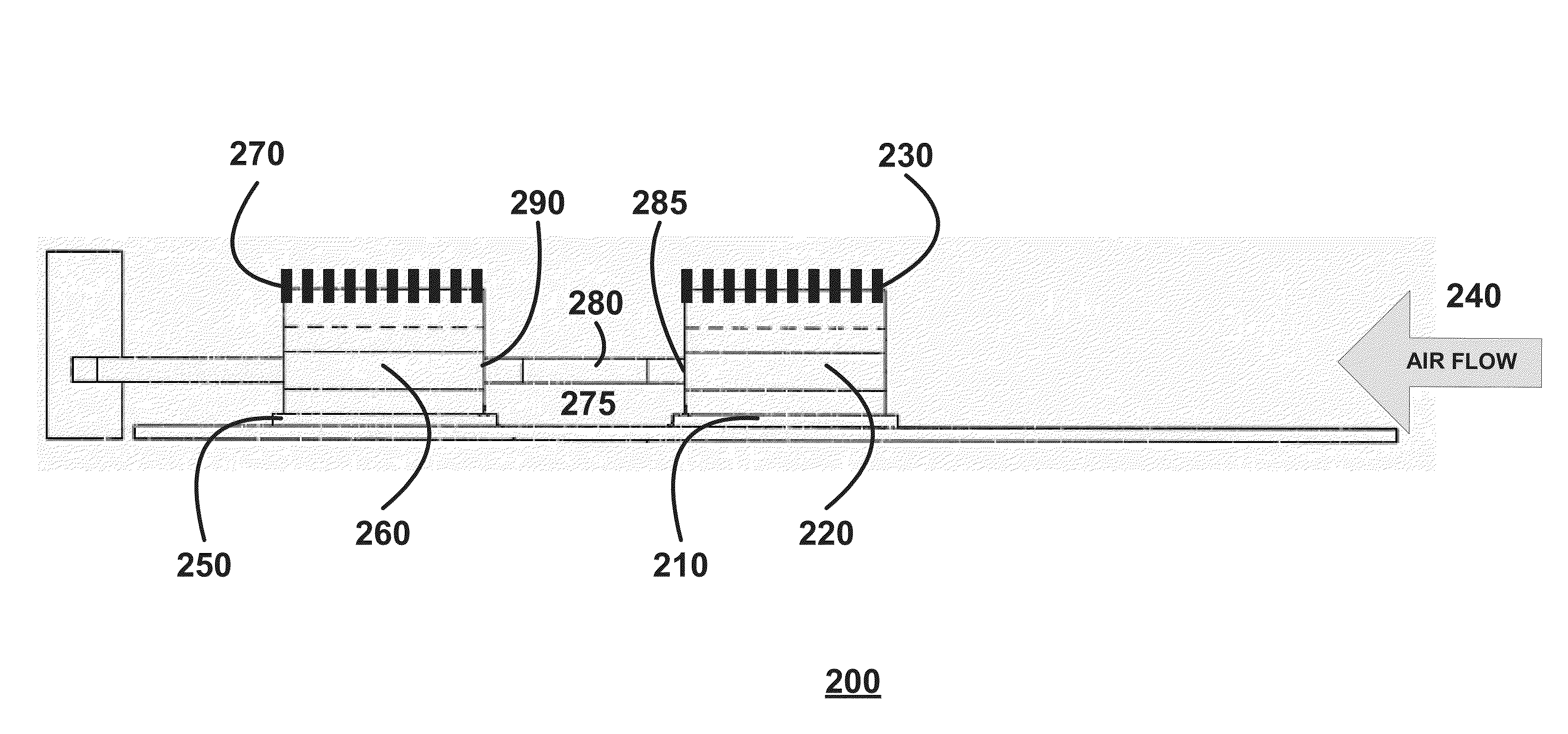
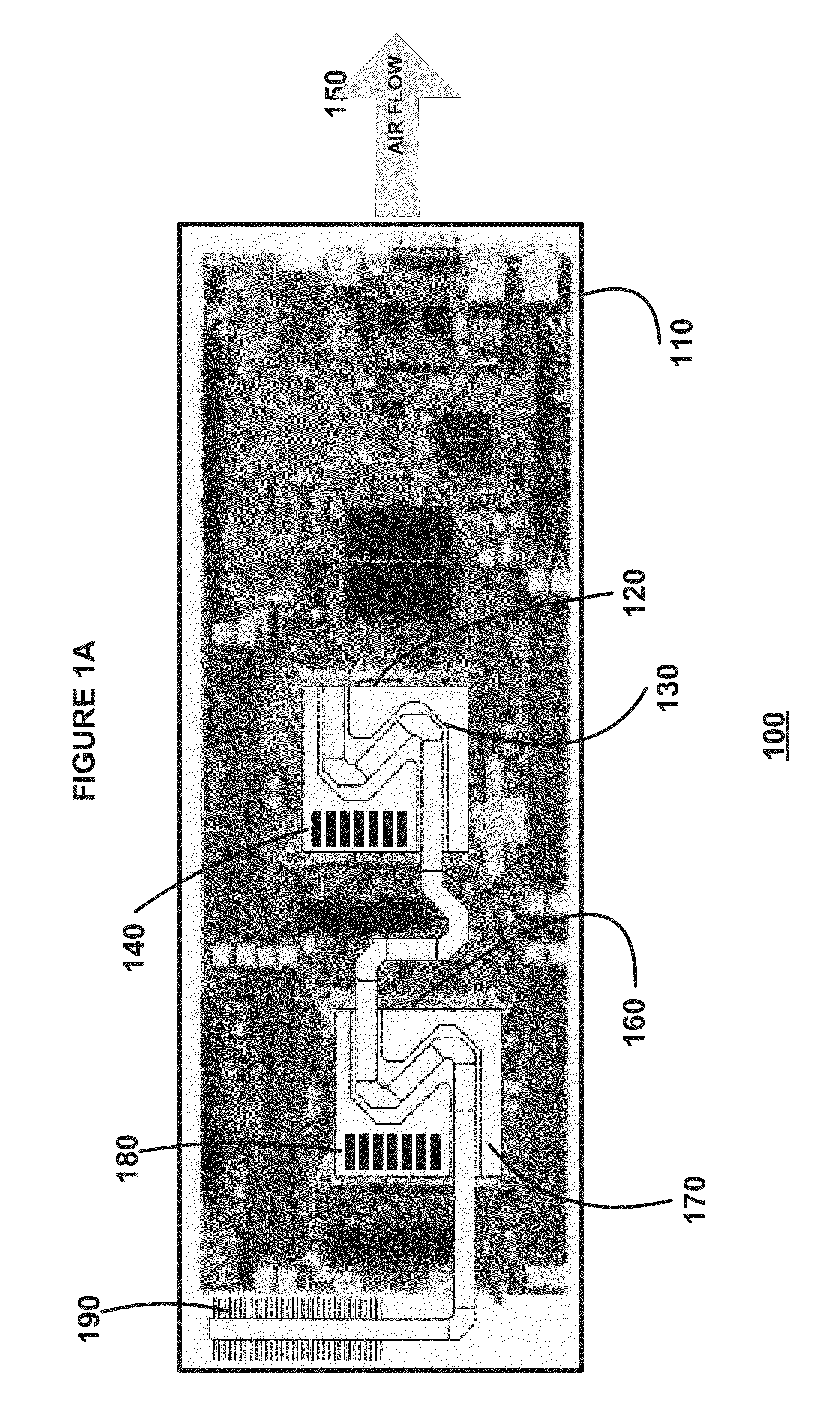
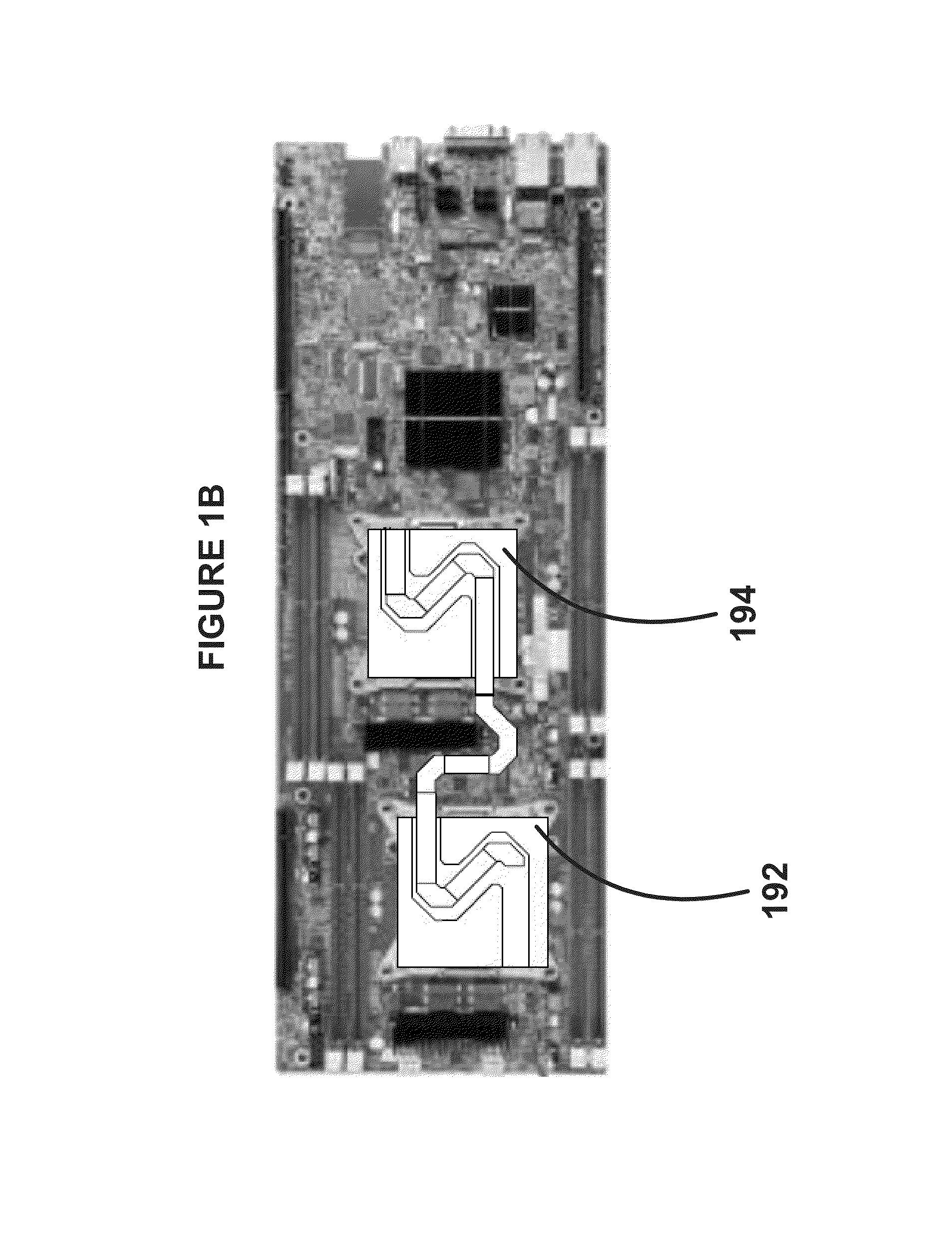
[0016]A system for cooling multiple in-line CPUs in a confined enclosure is provided. The cooling system of the present invention provides for improved overall system performance and reliability in computer systems employing multiple in-line CPUs in a confined enclosure such as a server tray or server blade. The system does so primarily by better equalizing the temperature of the leading CPU and the trailing CPU, reducing the temperatures on the trailing CPU. This is accomplished by reducing the amount of air flow that would otherwise be physically blocked by the heat sink of the front CPU as the air flow travels towards the heat sink of the rear CPU. It can also be achieved by physically connecting the two (or more) heat sinks with flexible heat pipes or the two approaches can be combined. The system provides the cost-effectiveness of traditional air cooling systems (as opposed to expensive liquid cooling systems) without requiring the use of an external radiator or fan. Because th...


PUM


Abstract

A system for cooling multiple in-line CPUs in a confined enclosure is provided. In an embodiment, the system may include a front CPU and a front heat sink that may be coupled to the front CPU. The front heat sink may have a plurality of fins and a corresponding fin pitch. The system may further include a rear CPU disposed in line with the front CPU and a rear heat sink coupled to the rear CPU. The rear heat sink may have a plurality of fins and a corresponding fin pitch. The fin pitch of the rear heat sink may be higher than the fin pitch of the front heat sink. In another embodiment, the front and rear heat sinks may be coupled together by one or more heat pipes.

Description

CROSS-REFERENCE TO RELATED APPLICATIONS[0001]The present application claims the priority benefit of U.S. provisional application No. 61 / 786,416, titled “SYSTEM FOR COOLING MULTIPLE IN-LINE CENTRAL PROCESSING UNITS IN A CONFINED ENCLOSURE,” filed Mar. 15, 2013, the disclosure of which is incorporated herein by reference.BACKGROUND[0002]1. Field of the Invention[0003]The present invention relates to cooling central processing units (CPUs). More specifically, the present invention relates to a system for cooling multiple in-line CPUs in a confined enclosure such as a sever tray or server blade.[0004]2. Description of the Related Art[0005]Modern CPUs are becoming increasingly powerful at a rapid rate. As CPU technologies progress, manufacturers are also continuously condensing these more powerful CPUs into smaller form factors. As a result, modern CPUs achieve high power densities in which they can exercise significant computing power without occupying significant space within computer ...

Claims


Application Information

Patent Timeline
Patent Type & Authority Applications(United States)
IPC IPC(8): H05K7/20
CPCH05K7/20709H05K7/20809H01L2924/0002H01L23/427H01L23/467H01L2924/00
Inventor VAN PELT, KEVIN LEEJOHNSON, THEODORE ROBERTKINSTLE III, ROBERT MICHAEL
Owner RPX CORP
Why Eureka
Try Eureka