
Anti-rotation device and method of use

a technology of anti-rotation device and method of use, which is applied in the direction of article separation, de-stacking articles, thin material processing, etc., can solve the problems of tearing, folding, and/or other damage to the article, so as to reduce the amount of folding and tearing, and reduce the rotation of the article

Active Publication Date: 2014-09-18
US POSTAL SERVICE
View PDF9 Cites 15 Cited by
  • Summary
  • Abstract
  • Description
  • Claims
  • Application Information

AI Technical Summary

Benefits of technology

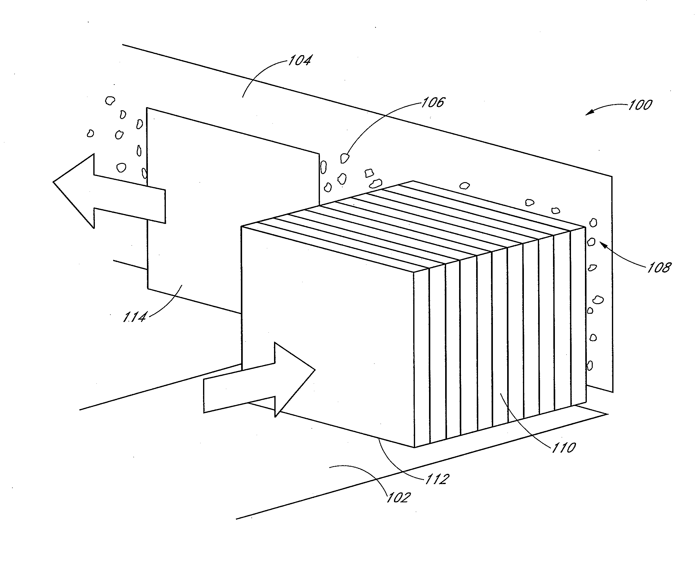
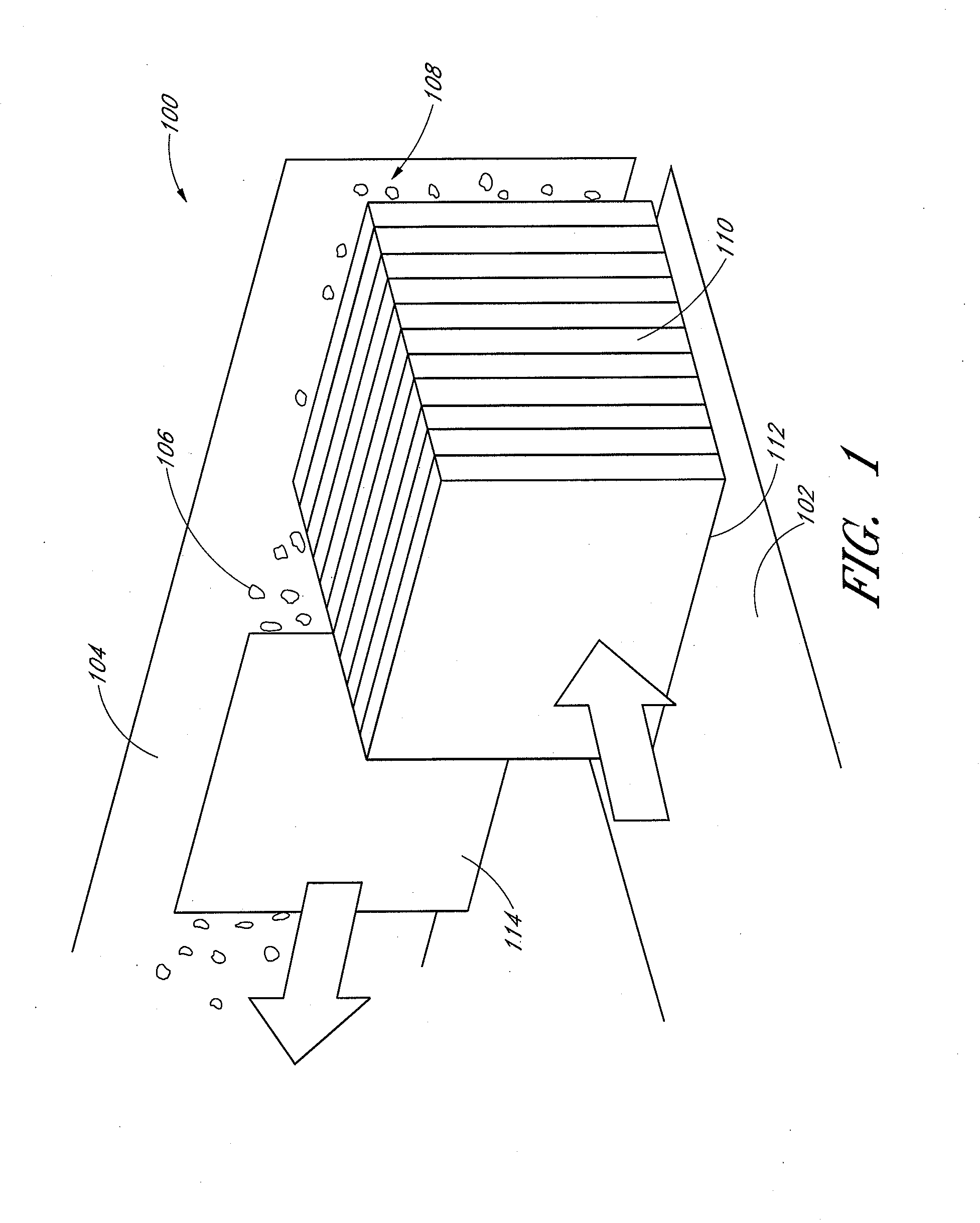
The present invention is about devices and methods used to reduce damage to articles during the process of separating and sorting them. The devices apply a frictional force to the back surface of an article while suction and an accelerating force are applied to the front surface. This friction holds the article together, resisting tearing or folding, and causes it to move as a single unitary article. Other aspects of the invention include a system for moving a stack of articles forward and a method of applying a force to a forward-most article to resist its upward motion during acceleration. The invention reduces damage to articles in the stack and improves the overall quality of the finished product.

Problems solved by technology

Such a design frequently causes problems when used to sort some articles, such as magazines, catalogs, and other similar items having a plurality of unbound edges.
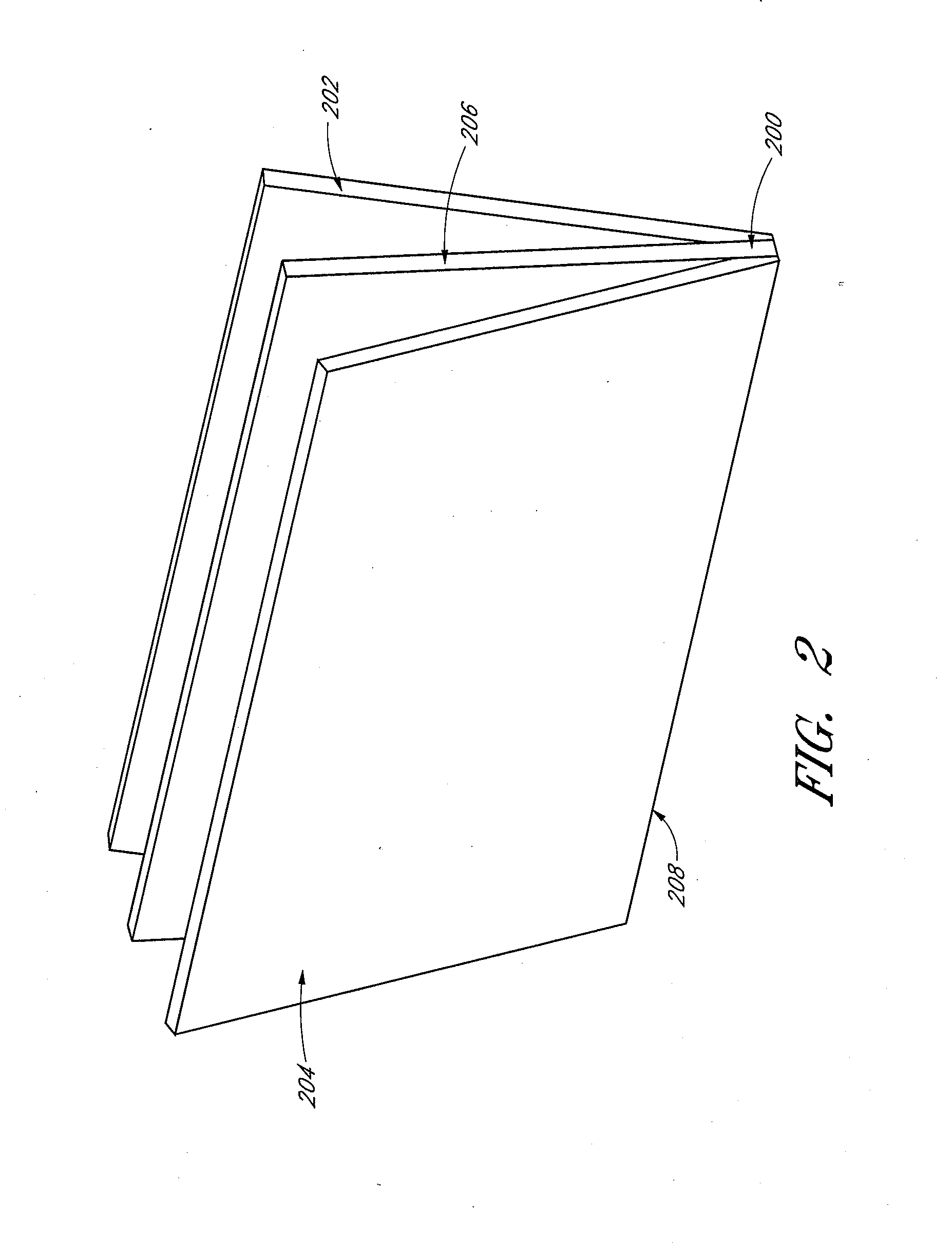
In such situations, at least some of the internal pages and the back cover resist the directional change in motion, possibly resulting in folding, tearing, and / or other damage to the article.

Method used


Image

  • Anti-rotation device and method of use
  • Anti-rotation device and method of use
  • Anti-rotation device and method of use

Examples


Embodiment Construction

[0031]In the following detailed description, reference is made to the accompanying drawings, which form a part of the present disclosure. The illustrative embodiments described in the detailed description, drawings, and claims are not meant to be limiting. Other embodiments may be utilized, and other changes may be made, without departing from the spirit or scope of the subject matter presented here. It will be readily understood that the aspects of the present disclosure, as generally described herein, and illustrated in the Figures, can be arranged, substituted, combined, and designed in a wide variety of different configurations, all of which are explicitly contemplated and form part of this disclosure.

[0032]To assist in the description of the devices and methods described herein, some relational and directional terms are used. “Connected” and “coupled,” and variations thereof, as used herein include direct connections, such as being contiguously formed with or attached directly ...


PUM


Abstract

A device for reducing rotation of an article during singulation of a stack of articles is disclosed. The device may include a torsion element, a rotatable member configured to rotate about an elongated axis of the torsion element between a first position and a second position, and a revolving member coupled to the rotatable member. An outer surface of the revolving member contacts a drive belt in the first position and an article in the second position. The torsion element exerts torque on the rotatable member when it moves from the first position towards the second position. The torque causes the outer surface of the revolving member to apply a frictional force to the article, thereby minimizing rotation of the article. Systems and methods of singulating articles are also disclosed.

Description

BACKGROUND[0001]1. Technical Field[0002]The disclosure relates to the field of automatic separation of items. More specifically, the present disclosure relates to the automatic singulation of articles from a bulk stack of articles.[0003]2. Description of the Related Art[0004]Articles, such as items of mail, are frequently provided in bulk and must be separated in order to properly sort and route each article. The process of separating a bulk stack of articles into individual articles, known as singulation, can be done automatically by placing the bulk stack of articles into a feeder. Current feeders include one or more conveyor belts for moving the articles, as well as a vacuum for applying suction to one side of an article piece positioned at the front of the bulk stack. This suction works to separate the lead article from the remainder of the bulk stack. The lead article can then be moved by a conveyor belt in a direction different from the direction of the bulk stack. Such a desi...

Claims


Application Information

Patent Timeline
IPC IPC(8): B65H3/66B65H3/12
CPCB65H3/124B65H3/66B65H2404/1521B65H2404/1532B65H1/025B65H7/16B65H2701/1916B65H2402/54B65H2515/20
Inventor BROWN, JOHN W.HOUSTON, EDWARD F.ROMAN, JUAN A.SHIU, LEUNG M.MAYHALL, RILEY H.MCCONNELL, WILLIAM P.GOOD, MATTHEW G.HUME, ROBERT E.HILLERICH, JR., THOMAS A.HA, LONG K.
Owner US POSTAL SERVICE
Learn More