Spinal implants and implantation system
a technology applied in the field of spinal implants and implantation systems, can solve the problems of limited minimally invasive placement of prior systems, and achieve the effects of increasing distance, facilitating fusion, and stabilizing and supporting the compressive load of the spin
- Summary
- Abstract
- Description
- Claims
- Application Information
AI Technical Summary
Benefits of technology
Problems solved by technology
Method used
Image
Examples
use examples
Method of Use Examples
[0142]While the particulars of the tools for deployment of the implants are briefly illustrated herein, a detailed description is beyond the focus of this Provisional application although the implant deployment tools (e.g., insertion tools; retention tools; extraction tools, and tools that may be used for both insertion and extraction) are contemplated. As used herein in this disclosure and application, it will be understood that the terms insertion tool, retention tool and extraction tool are sometimes used interchangeably or collectively and refer to the movement and manipulation of a spinal implant of the present disclosure. Moreover, it will be understood that a tool may serve individual and / or multiple purposes. A brief outline of the intended method of use / deployment of certain devices of the present disclosure is provided below.
example a
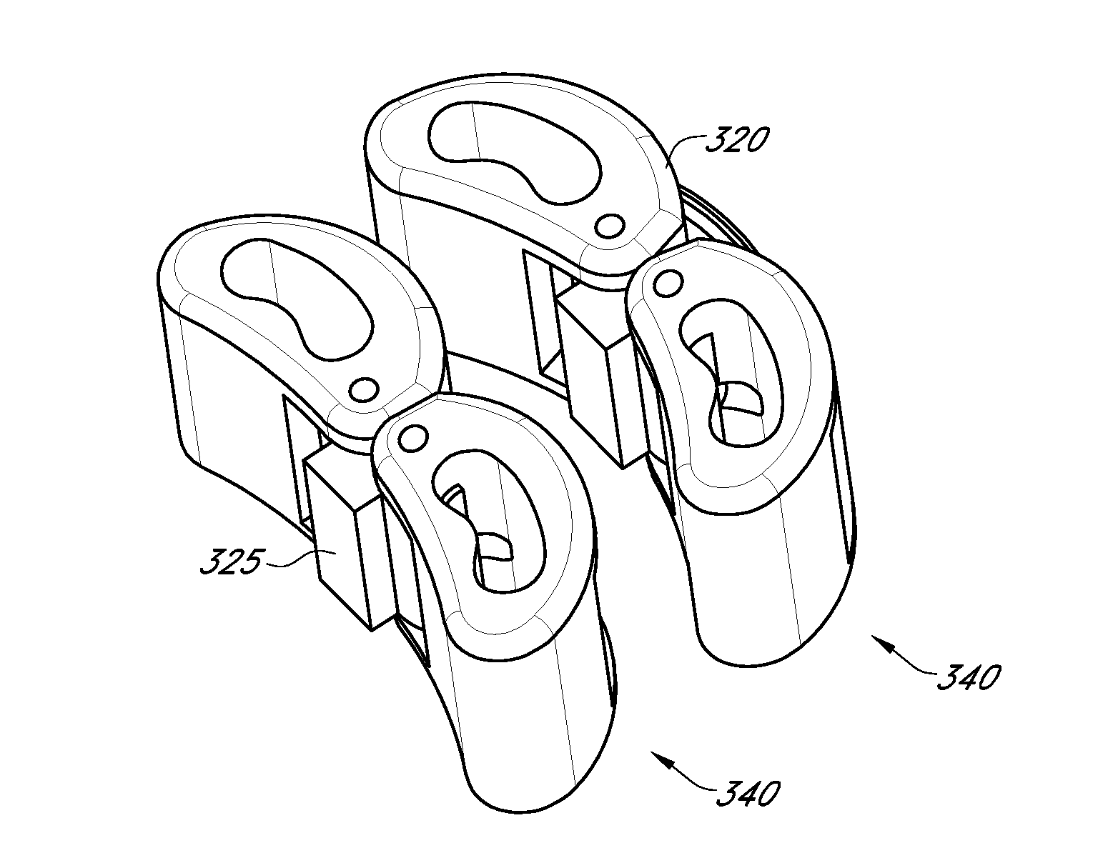
Mini-Cage
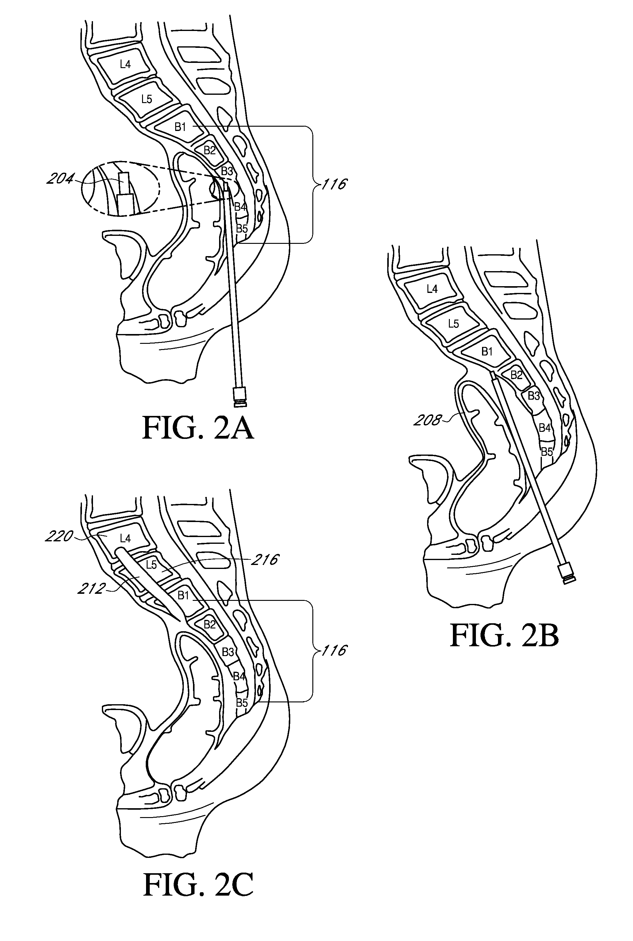
[0143]Access and establish trajectory using dissector and beveled guide pin
[0144]6 mm, 8 mm, 10 mm dilator and sheath
[0145]9 mm drill through sacrum
[0146]L5 / S1 discectomy using AXIALIF® discectomy tools (insert initial graft material)
[0147]12 mm dilator and sheath
[0148]10.5 mm drill through sacrum
[0149]Advance sheath opening to S1 endplate
[0150]Deploy mini-cage(s) (All concepts)
[0151]May deploy one or multiple cages (or cage constructs) in any radial direction (anterior, anterio-lateral, lateral, posterior)
[0152]May deploy taller cage or cage construct in anterior direction for lordosis and shorter cage or cage construct posterior
[0153]Cage may have lordotic angle to fit L5 / S1 endplate angle
[0154]Cage may have wedge design to self-distract disc space
[0155]Dimensional ranges: Diameter for deployment through a tube=9 mm-16 mm (this would cover deployment 10 mm sheath up to tubular retractor); Height=7 mm-17 mm; Lordotic Angles—0°-10° and / or 0°-20°
[0156]Insert secondary graft ...
example b
Mini-Cage with Expanding Sacral Plug or Axial Threaded Cage
[0158]Access and establish trajectory using dissector and beveled guide pin
[0159]6 mm, 8 mm, 10 mm dilator and sheath
[0160]9 mm drill through sacrum
[0161]L5 / S1 discectomy using AXIALIF® discectomy tools (insert initial graft material)
[0162]12 mm dilator and sheath
[0163]10.5 mm drill through sacrum
[0164]Advance sheath opening to S1 endplate
[0165]Deploy mini-cage(s) (All concepts)
[0166]May deploy one or multiple cages (or cage constructs) in any radial direction (anterior, anterio-lateral, lateral, posterior)
[0167]May deploy taller cage or cage construct in anterior direction for lordosis and shorter cage or cage construct posterior
[0168]Cage may have lordotic angle to fit L5 / S1 endplate angle
[0169]Cage may have wedge design to self-distract disc space
[0170]Dimensional ranges: Diameter for deployment through a tube=9 mm-16 mm (this would cover deployment 10 mm sheath up to tubular retractor); Height=7 mm-17 mm; Lordotic Angles...
PUM
 Abstract
Description
Claims
Application Information
 - R&D
- Intellectual Property
- Life Sciences
- Materials
- Tech Scout
- Unparalleled Data Quality
- Higher Quality Content
- 60% Fewer Hallucinations
Browse by: Latest US Patents, China's latest patents, Technical Efficacy Thesaurus, Application Domain, Technology Topic, Popular Technical Reports.
© 2025 PatSnap. All rights reserved.Legal|Privacy policy|Modern Slavery Act Transparency Statement|Sitemap|About US| Contact US: help@patsnap.com


