Rotary wing aircraft with a hybrid power plant

a hybrid power plant and rotary wing technology, applied in the field of rotary wing aircraft, can solve the problems of reducing the specific fuel consumption of the aircraft, reducing the efficiency of the power plant, and being difficult to design, adapt and implement a hybrid power plant and its configuration

Active Publication Date: 2014-09-25
EUROCOPTER
View PDF3 Cites 71 Cited by
  • Summary
  • Abstract
  • Description
  • Claims
  • Application Information

AI Technical Summary

Benefits of technology

[0033]In addition, if necessary the second connection means make it possible for a gas generator to co-operate with an electrical machine.
[0070]In addition, the second connection means then make it possible in particular for the electrical machine to transform mechanical energy coming from the engine into electrical energy while in flight, for example, and to transform electrical energy into mechanical energy in order to drive the gas generator.

Problems solved by technology

That type of configuration is advantageous, but it can be relatively heavy and bulky by ensuring redundancy for the electrical machines.
The engine then runs the risk of operating at a compression ratio that is not optimized, thereby leading to a drop in its specific fuel consumption.
In conclusion, it can be understood that it is not easy to design, adapt, and implement a hybrid power plant and its configuration.

Method used


Image

  • Rotary wing aircraft with a hybrid power plant
  • Rotary wing aircraft with a hybrid power plant
  • Rotary wing aircraft with a hybrid power plant

Examples


first embodiment

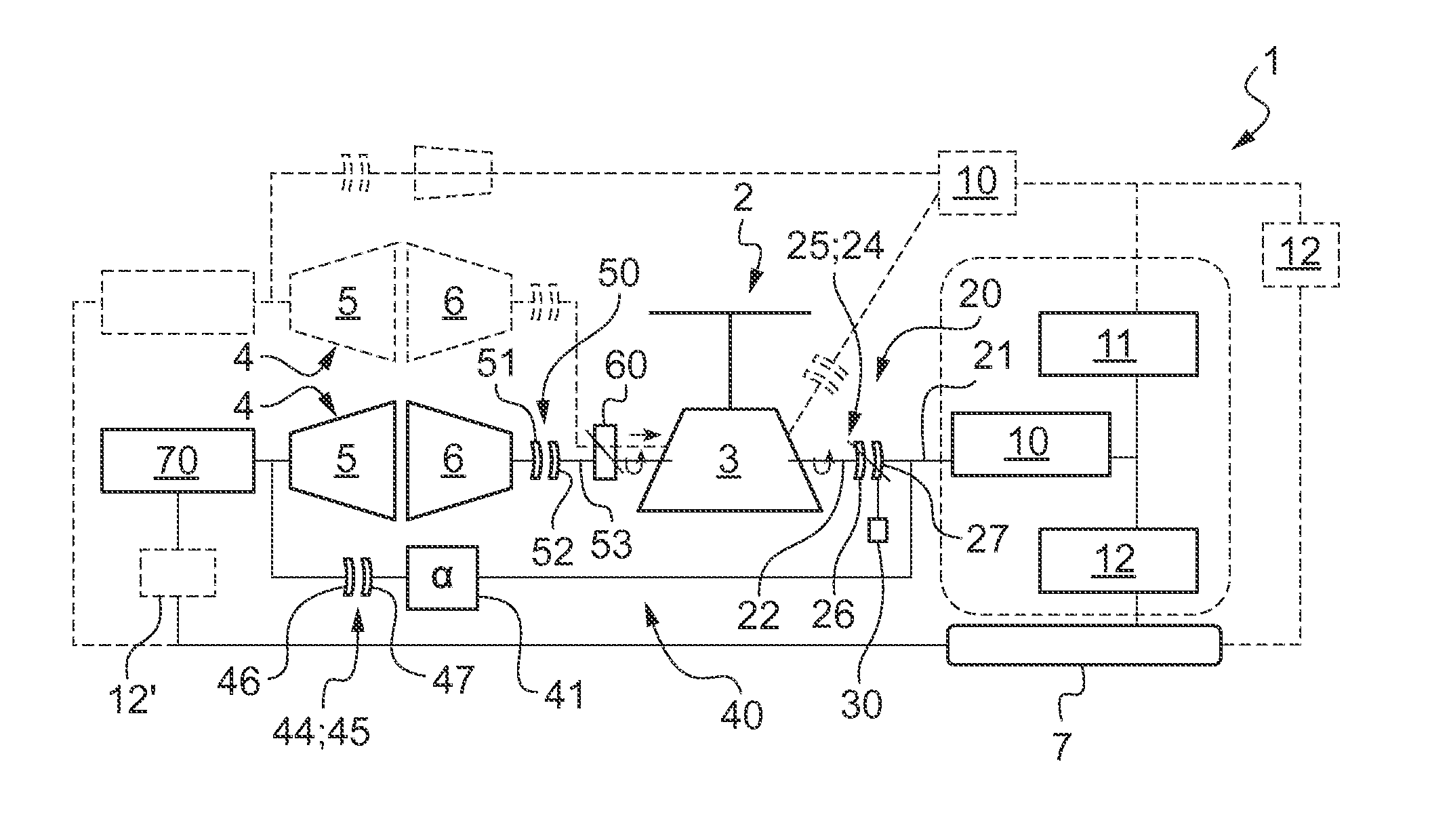
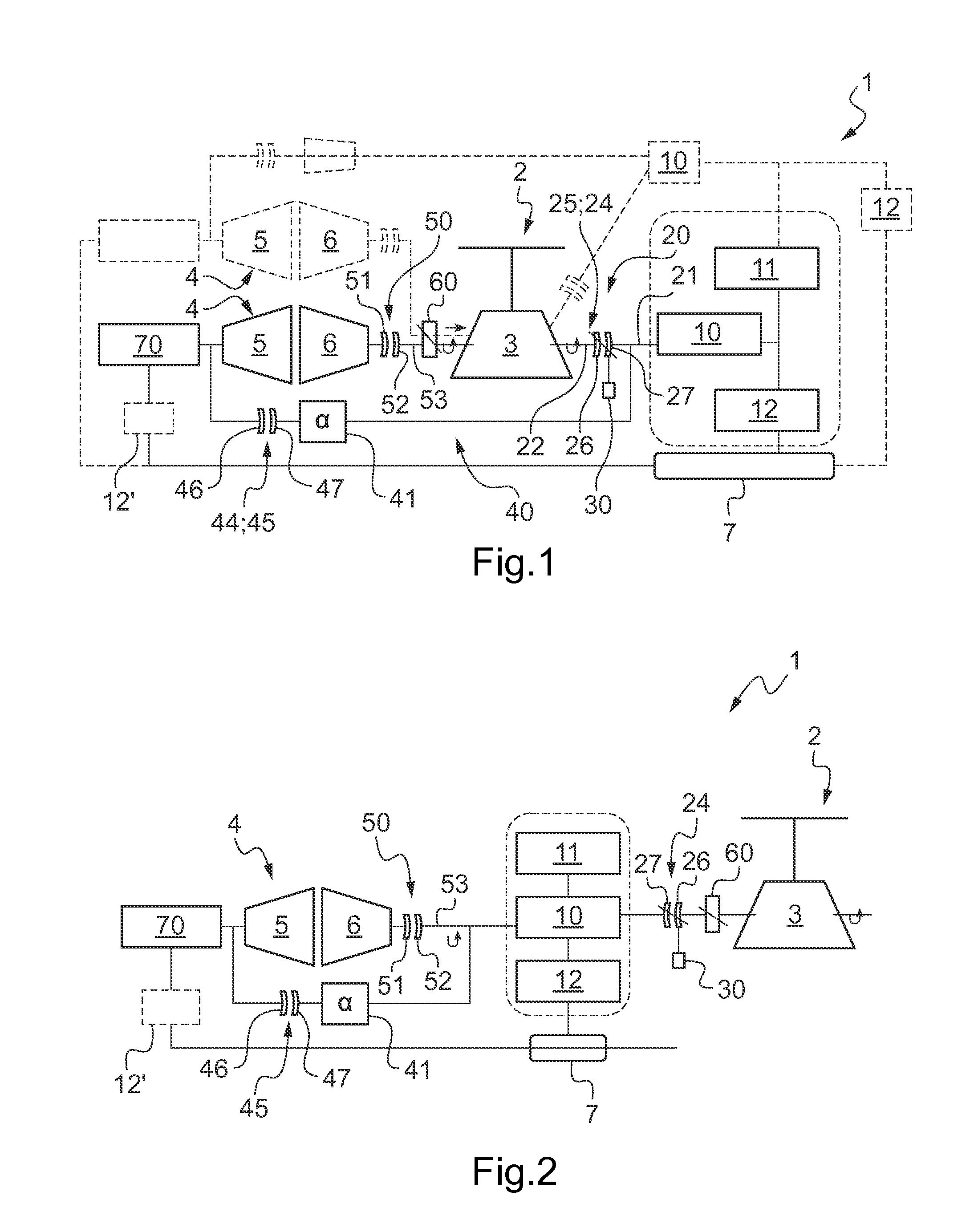
[0120]In this first embodiment, an engine is associated with an electrical machine and with an electric motor 70.

[0121]The electric motor 70 is thus mechanically connected to a generator via a mechanical power transmission train, the second connection means 40 possibly leading to this transmission train. The electric motor 70 is also electrically connected to the on-board electricity network 7, optionally via a power converter 12′ if the voltage levels of the electric motor 70 and of the electricity network 7 are different.

[0122]In this first embodiment, the second connection means are provided with a freewheel 45 and with mechanical means 41 presenting a predetermined transmission ratio α. The freewheel 45 is provided with a driving portion 46 mechanically connected to a gas generator 5 and a driven portion 47 mechanically connected to the mechanical means 41. The transmission ratio α is greater than the quotient of the maximum speed of rotation of the gas generator divided by the ...

second embodiment

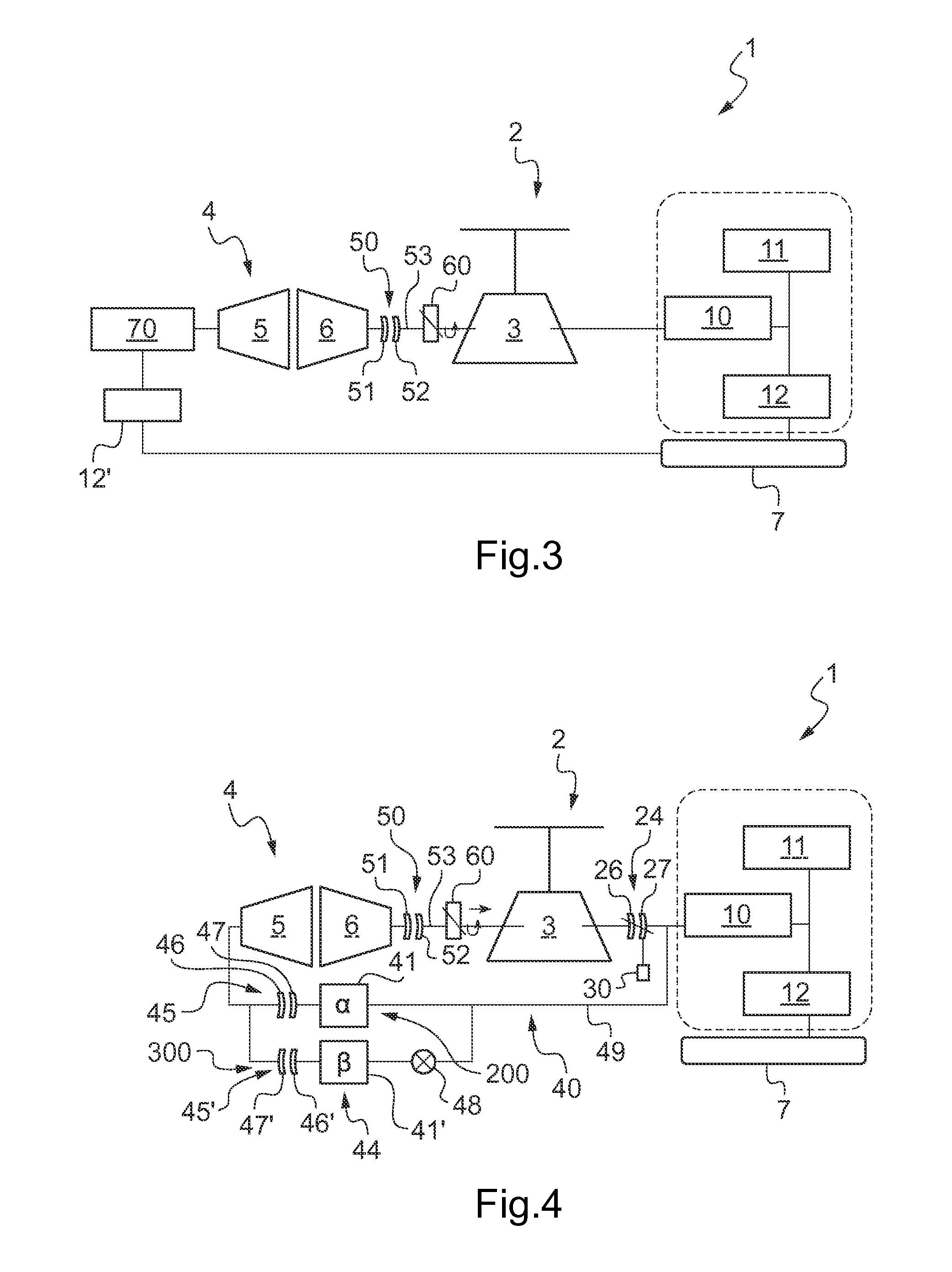
[0134]FIGS. 4 to 9 show variants of a

[0135]This second embodiment consists in using at least one electrical machine. Under such circumstances, this second embodiment does not have the electric motor used in the first embodiment.

[0136]FIGS. 4 and 5 show a first version of the second embodiment. More precisely, FIG. 4 shows a first version of the second embodiment using an electrical machine in a first arrangement, while FIG. 5 shows a first version of the second embodiment using an electrical machine in the second arrangement.

[0137]In this first version, and with reference to FIG. 4, the second connection means 40 comprise two mechanical systems 200 and 300 arranged in parallel and mechanically connected by an intermediate shaft 49 to an electrical machine 10. These two mechanical systems 200 and 300 are also mechanically connected by a mechanical transmission train to a gas generator.

[0138]It should be observed that the term “shaft” is used to designate a mechanical connection invol...


PUM


Abstract

An aircraft (1) having at least one rotor (2) driven by a main gearbox (3), at least one fuel-burning engine (4), an on-board electricity network (7), and at least one electrical machine (10) corresponding to the engine (4) and capable of operating both in electric motor mode and also in electricity generator mode, each electrical machine (10) being mechanically connected to said main gearbox (3) by first connection means (20) and being electrically connected to said on-board electricity network (7). Second mechanical connection means (40) connect each electrical machine (10) mechanically to a gas generator (5) of an engine.

Description

CROSS REFERENCE TO RELATED APPLICATION[0001]This application claims priority to French patent application No. FR 13 00683 filed on Mar. 25, 2013, the disclosure of which is incorporated in its entirety by reference herein.BACKGROUND OF THE INVENTION[0002](1) Field of the Invention[0003]The present invention relates to a rotary wing aircraft that has a hybrid power plant.[0004]The present invention thus relates to the field of aircraft that include in particular a rotary wing. More particularly, the invention relates to aircraft having a so-called “hybrid” power plant for driving rotation of at least one rotor of a rotary wing via a main gearbox of the aircraft. Such a main gearbox is referred to more simply by its initials “main gearbox”.[0005](2) Description of Related Art[0006]A “hybrid” power plant designates an installation having at least one fuel-burning engine and at least one electrical member, each of them being suitable for driving the main gearbox.[0007]The electrical mem...

Claims


Application Information

Patent Timeline
Patent Type & Authority Applications(United States)
IPC IPC(8): F02C7/36
CPCF02C7/36B60K6/383B60K6/48B64C27/12B60K2006/268B64D2027/026B64D27/24Y02T10/62Y02T50/60Y02T50/40
Inventor MARIOTTO, DAMIENCONNAULTE, MATTHIEU
Owner EUROCOPTER
Why Eureka
Try Eureka