Supercharge Your Innovation With Domain-Expert AI Agents!

Sensor Device Having Plural Resistance Change Type Sensors and Method of Using the Same

a technology of resistance change and sensor, which is applied in the direction of electrographic process, using mechanical means, instruments, etc., can solve the problem of inconvenient replacement of the sensor devi

Active Publication Date: 2014-09-25
BROTHER KOGYO KK
View PDF8 Cites 2 Cited by
  • Summary
  • Abstract
  • Description
  • Claims
  • Application Information

AI Technical Summary

Benefits of technology

The invention provides a sensor device with multiple resistance change sensors. The number of lines used to transmit sensor output doesn't need to change as the number of sensors increases. This simplifies the design and improves efficiency.

Problems solved by technology

However, it is inconvenient for the sensor device to replace or re-design the controller so as to be capable of accepting an increased number of outputs from the increased number of sensors.

Method used


Image

  • Sensor Device Having Plural Resistance Change Type Sensors and Method of Using the Same
  • Sensor Device Having Plural Resistance Change Type Sensors and Method of Using the Same
  • Sensor Device Having Plural Resistance Change Type Sensors and Method of Using the Same

Examples


Embodiment Construction

[0028]One embodiment of the invention will be described with reference to the accompanying drawings.

[0029]

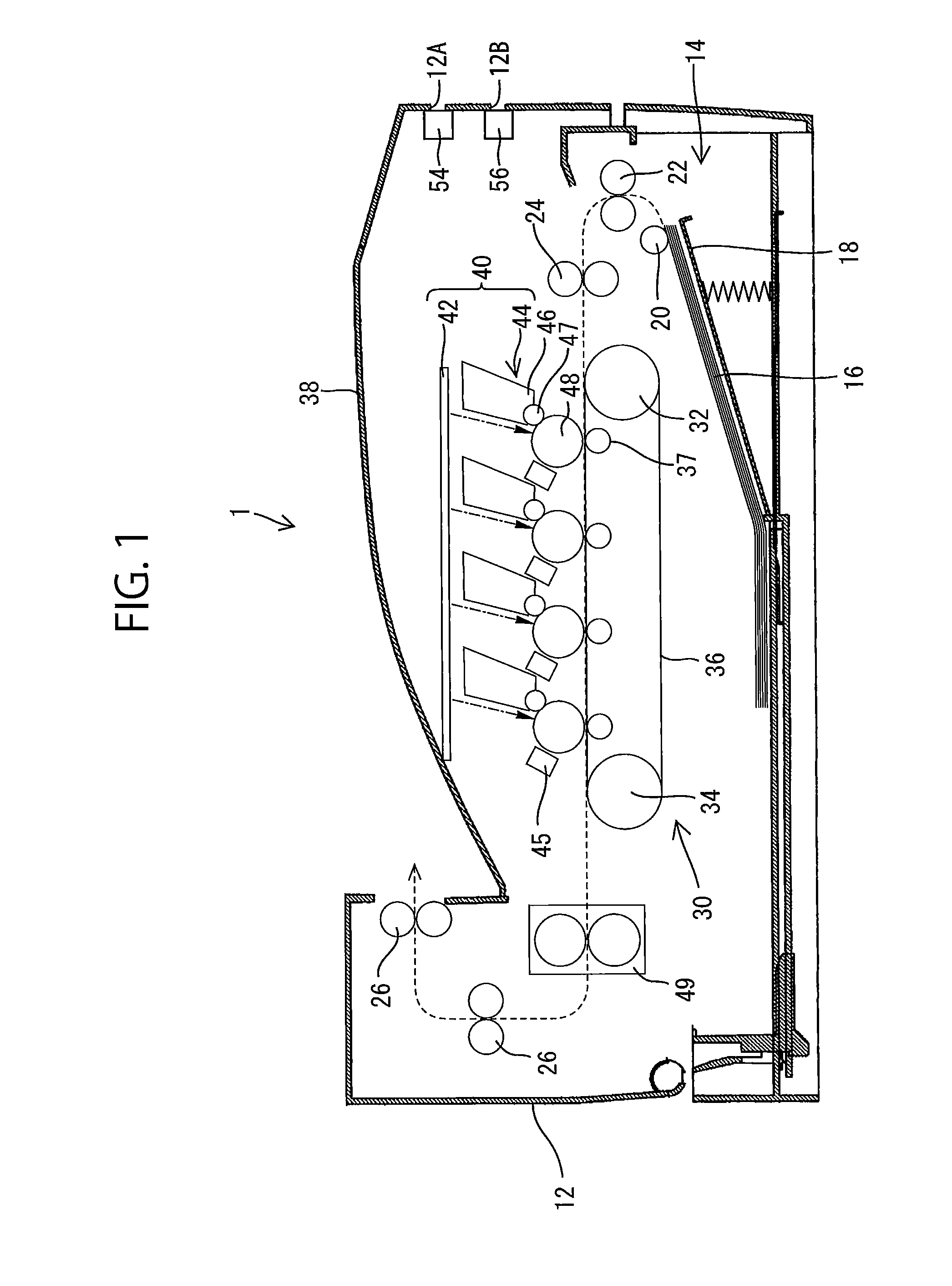
[0030]FIG. 1 is a vertical cross-sectional view of a printer 1, which is one of image forming devices, according to one embodiment of the invention. As shown in FIG. 1, the printer 1 is a direct-transfer, tandem type color laser printer capable of forming a full-color image using four kinds of color toner of yellow, magenta, cyan and black.

[0031]A print medium storage tray 14 is accommodated in a casing 12 of the printer 1 and disposed in the lower portion thereof. A plenty of sheet-type print media 16, such as sheets of paper, is stacked in the tray 14. The tray 14 is capable of being drawn out of the casing 12 for the user to supplement the print media 16. Upon completion of supplementing the print media 16, the tray 14 is returned to the right position within the casing 12. The print media stacked in the tray 14 is urged against a pickup roller 28 by a pressing plate 18 upwar...


PUM

PropertyMeasurementUnit
temperatureaaaaaaaaaa
relative humidityaaaaaaaaaa
resistanceaaaaaaaaaa

Abstract

To detect humidity, used are a first series connection circuit connecting a thermistor and a fixed resistor via a node, a second series connection circuit connecting a resistance change type humidity sensor and the thermistor via the node, and a third series connection circuit connecting the humidity sensor and the fixed resistor via the node. A predetermined voltage is applied across the first circuit to detect a first voltage indicating temperature through the node, and secondly across the second circuit to detect a second voltage indicating a first humidity through the node, and finally across the third circuit to detect a third voltage indicating a second humidity through the node. Then, the first voltage is compared with a reference voltage and judgment is made, based on a comparison result, to determine which of the second voltage and the third voltage is relevant to use as a basis for outputting the humidity as detected.

Description

CROSS REFERENCE TO RELATED APPLICATION[0001]This application claims priority from Japanese Patent Application No. 2013-062089 filed Mar. 25, 2013. The entire content of the priority applications is incorporated herein by reference.BACKGROUND[0002]1. Field of the Invention[0003]The present invention relates generally to a sensor device and a method of using the same, and more particularly, to a sensor device having a plurality of resistance change type sensors (or variable resistance sensors) for sensing, for example, humidity and temperature.[0004]2. Description of the Related Art[0005]Japanese Patent Application Publication No. 2009-180560 discloses a sensor device having a detecting part and a controller, in which the outputs of the detecting part are applied to the controller. The detecting part includes a plurality of resistance change type sensors. Each resistance change type sensor outputs a voltage changeable depending upon the resistance of the sensor which in turn is change...

Claims


Application Information

Patent Timeline
Patent Type & Authority Applications(United States)
IPC IPC(8): G01N27/12G03G15/00
CPCG01N27/048G03G2215/00084G03G21/203G01N27/121
Inventor ZHENG, JIEITO, RYOKANAZAWA, KENJITAKAHASHI, OSAMU
Owner BROTHER KOGYO KK
Features
  • R&D
  • Intellectual Property
  • Life Sciences
  • Materials
  • Tech Scout
  • Unparalleled Data Quality
  • Higher Quality Content
  • 60% Fewer Hallucinations
Learn More