Vane Electrostatic Precipitator

a precipitator and electrostatic technology, applied in the field of electrostatic precipitators, can solve the problems of poor conductive and high conductive particulates in the prior art of precipitators, and achieve the effect of efficient processing and efficient collection of particulates

Inactive Publication Date: 2014-09-25
DUNN JOHN P
View PDF12 Cites 13 Cited by
  • Summary
  • Abstract
  • Description
  • Claims
  • Application Information

AI Technical Summary

Benefits of technology

[0014]In one embodiment, a method for processing large volumes of entrained air and efficiently collecting particulates uses multiple vane electrodes that subdivide the main air stream into smaller individual air streams for more efficient processing rather than parallel plate electrodes found in standard electrostatic precipitators. This is preferably achieved by arranging the vane assembly so that they operate 3 to 80 degrees from the main air flow and the individual vanes operate at 45 to 95 degrees from the main air flow.

Problems solved by technology

Prior art precipitators have difficulty collecting highly conductive and very poorly conductive particulates.

Method used


Image

  • Vane Electrostatic Precipitator
  • Vane Electrostatic Precipitator
  • Vane Electrostatic Precipitator

Examples


Embodiment Construction

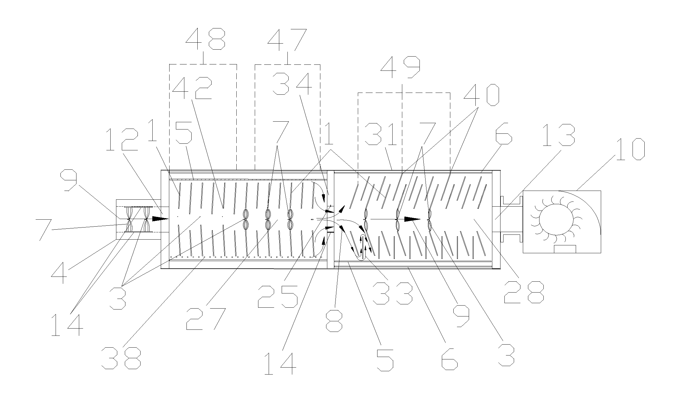
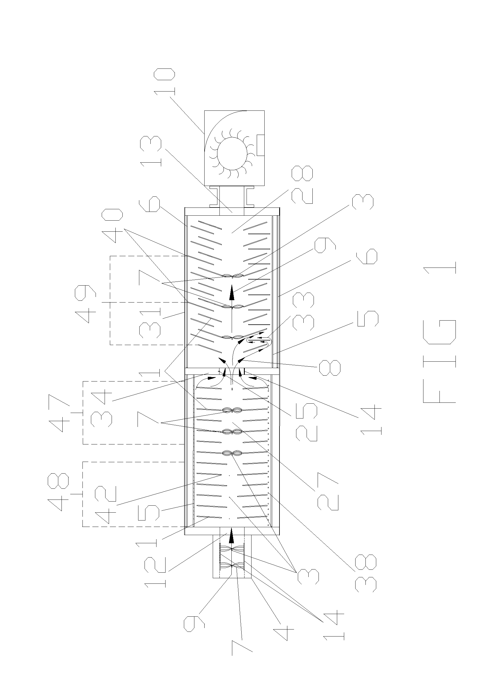
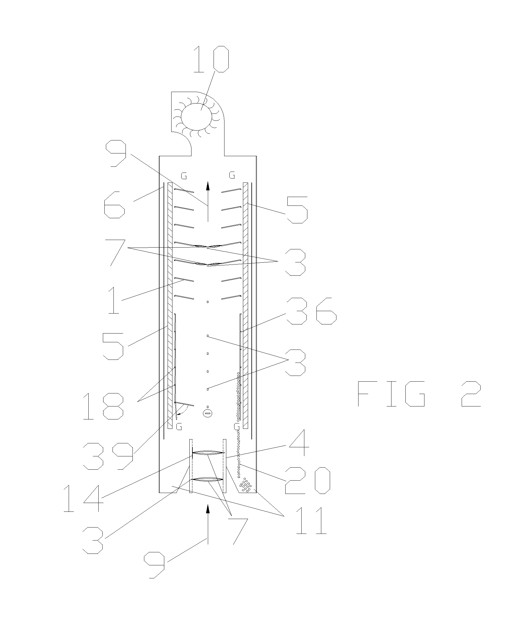
[0068]The terms “vane”, “vane electrode”, “vane type electrode” and “vane type collecting electrode” are used interchangeably herein. A vane assembly, as described herein, is a group of vanes that are structurally assembled as one unit. The terms “input and output orifice” and “input and output aperture” are also used interchangeably herein.

[0069]The vane electrostatic precipitator technology described herein improves on the development of a “Grid Electrostatic Precipitator” (GEP). Patents related to the GEP technology include U.S. Pat. No. 6,773,489, U.S. Pat. No. 7,105,041 and U.S. Pat. No. 7,585,352, the disclosures of which are herein incorporated by reference.

[0070]Some applications for the VEP technology include, but are not limited to, collecting fly-ash and other particles from coal fired burners (both small and large coal fired furnaces), collecting hazardous waste, collecting glass and ceramic dust particles, collecting smelter dust particles, cement manufacturing (and oth...


PUM


Abstract

Methods using vane electrostatic precipitators collect charged and uncharged particles with vane assemblies that are physically arranged to reduce the air flow rate to at or below 1.0 ft/sec (0.305 m/sec). In preferred embodiments, the main entrained air is divided into smaller proportions by using a plurality of vane assemblies in a vane electrostatic precipitator operating at a specific angle that have discharge electrodes in front of the vanes. This results in both the particles being charged and the flow rate of the air and articles being reduced as they traverse between vanes and over the vane surface. The vane width, operating angle, vane length and vane offset are designed to reduce the air flow rate. As a result, at the ends of the vanes, a high percentage of the air flow is less than 1 ft/s. This allows the particles that are discharged from the vanes during operation to fall by gravity and in the direction of lower air flow, resulting in extremely low re-entrainment and efficient particle collection.

Description

REFERENCE TO RELATED APPLICATIONS[0001]This application claims one or more inventions which were disclosed in Provisional Application No. 61 / 961,778, filed Oct. 23, 2013, entitled “VANE ELECTROSTATIC PRECIPITATOR”.[0002]This application is also a continuation-in-part of:[0003]Co-pending application Ser. No. 13 / 369,823, filed Feb. 9, 2012, entitled “VANE ELECTROSTATIC PRECIPITATOR”, which claims one or more inventions which were disclosed in Provisional Application No. 61 / 521,897, filed Aug. 10, 2011, entitled “VANE ELECTROSTATIC PRECIPITATOR (VEP)”.[0004]Co-pending application Ser. No. 13 / 724,286, filed Dec. 21, 2012, entitled “VANE ELECTROSTATIC PRECIPITATOR”.[0005]Co-pending application Ser. No. 13 / 792,408, filed Mar. 11, 2013, entitled “VANE ELECTROSTATIC PRECIPITATOR”.[0006]The benefit under 35 USC §119(e) of the United States provisional applications is hereby claimed, and the aforementioned applications are hereby incorporated herein by reference.BACKGROUND OF THE INVENTION[00...

Claims


Application Information

Patent Timeline
Patent Type & Authority Applications(United States)
IPC IPC(8): B03C3/47B03C3/36
CPCB03C3/47B03C3/363B03C2201/10B03C3/366B03C3/41B03C3/12
Inventor DUNN, JOHN P.
Owner DUNN JOHN P
Why Eureka
Try Eureka