
Internally actuated autonomous sailing buoy

a technology of autonomous sailing and internal actuation, which is applied in the direction of buoys, steering components, vessel movement reduction by mass displacement, etc., can solve the problems of very little maintenance and the deployment feature decreases operational costs, and achieves significant increase in resistance to harsh weather

Active Publication Date: 2014-09-25
PAASCH KASPER MAYNTZ
View PDF9 Cites 10 Cited by
  • Summary
  • Abstract
  • Description
  • Claims
  • Application Information

AI Technical Summary

Benefits of technology

The present invention is based on a new design for a sailing buoy that can be easily steered without any external moving parts. This design has increased resistance to harsh weather, which increases its lifespan. The buoy body has two appendages, one to catch the wind, and the other to play a role similar to a rudder. However, both appendages are completely rigid and fixed, without any actuation. This eliminates the need for an automatic moving mass system inside the buoy to replace the standard articulated rudder and sail for steering. This new buoy design has multiple applications, including improving the efficiency and decreasing the cost of data collection in the military. It also requires minimal maintenance compared to other autonomous vehicles in the surface ocean. Overall, this invention offers a more stable, efficient, and cost-effective solution for various applications.

Problems solved by technology

However, contrary to a sailboat, both of these appendages are completely rigid and fixed, i.e. not actuated.
The self-deployment feature decreases operational costs compared to traditional data buoys and full internal actuation induces very little maintenance compared to currently available surface autonomous vehicles.

Method used


Image

  • Internally actuated autonomous sailing buoy
  • Internally actuated autonomous sailing buoy
  • Internally actuated autonomous sailing buoy

Examples


Embodiment Construction

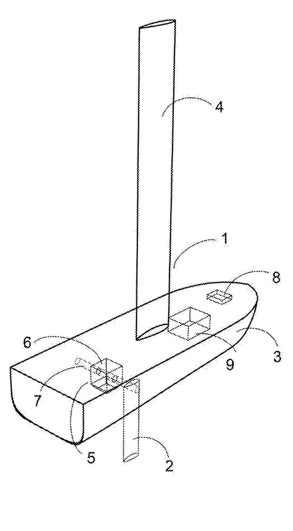
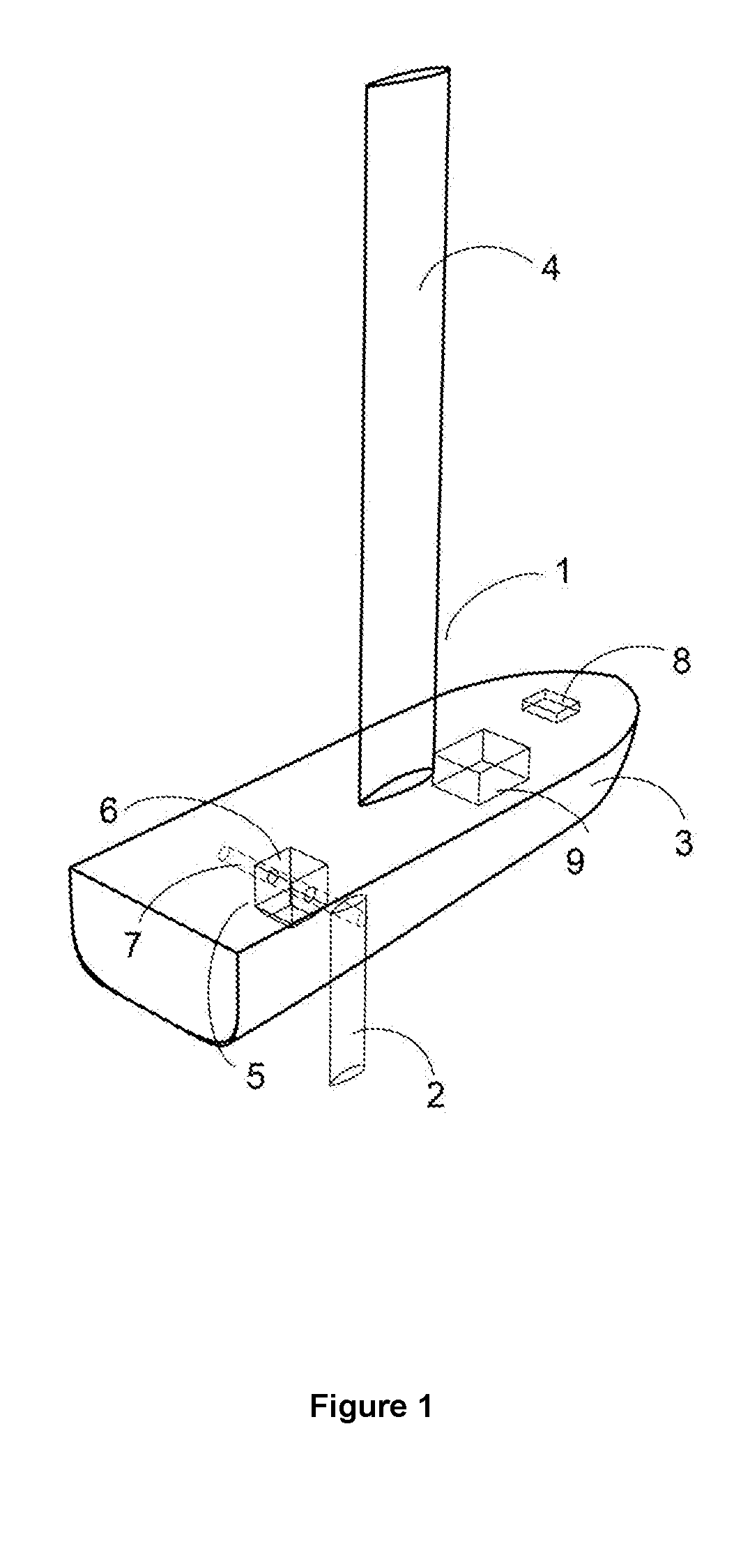
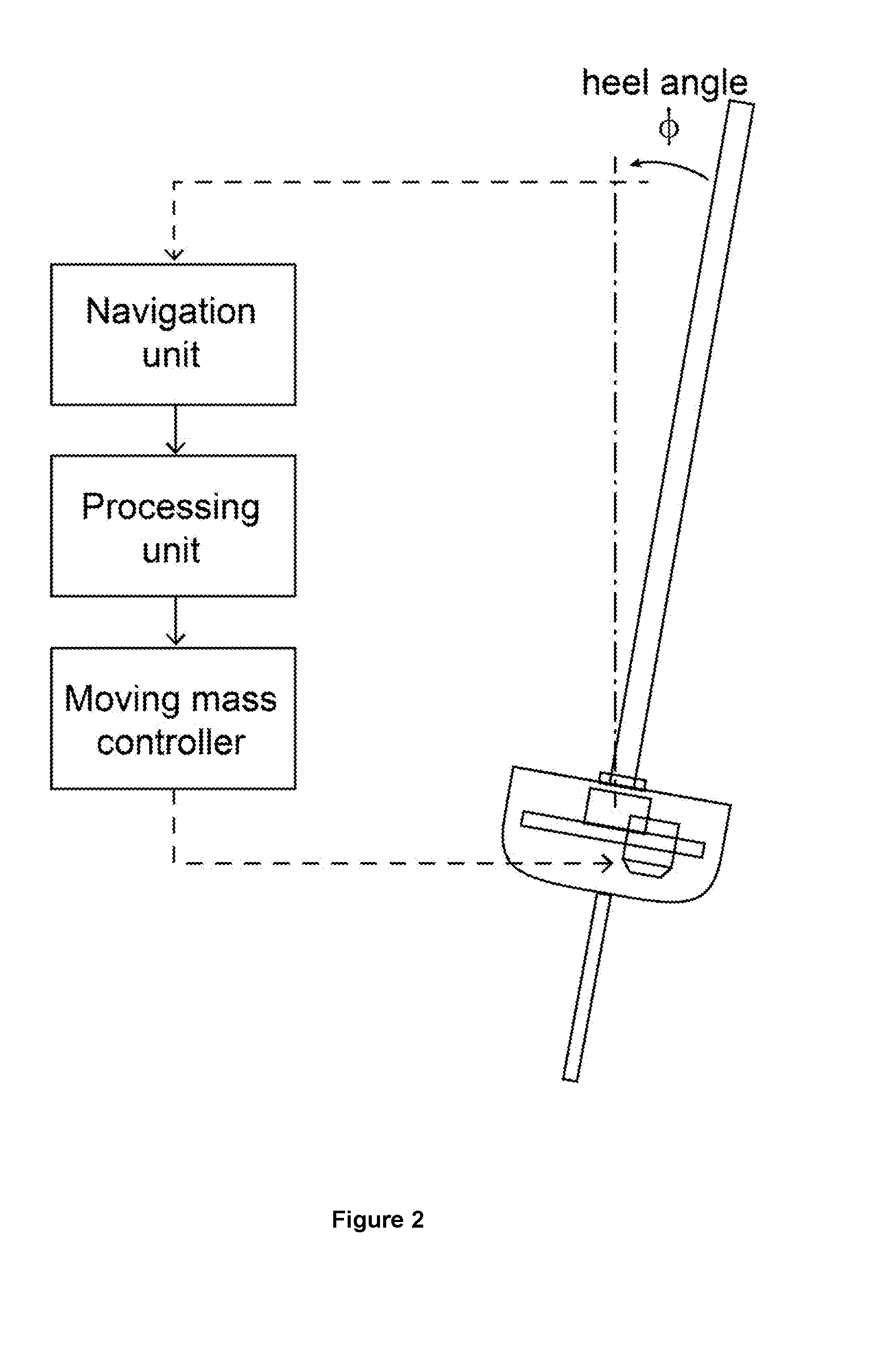
[0027]Referring to FIGS. 1 and 3A-B-C, the autonomous internally actuated sailing buoy is shown generally at 1. The buoy includes a keel 2 attached to the hull or buoy body 3, and a fixed rigid wing 4 for the sail, also attached to the buoy body 3. Since the keel 3 and the wing 4 have both a fixed position along the length of the body buoy, they can either be attached rigidly to the body buoy 3, or the three objects 2, 3 and 4 can be made together as a single rigid closed object, thus keeping the number of openings in the buoy body to a minimum and decreasing the need for water-proof joints. In order to make steering possible an automatic moving mass system 5 inside the buoy replaces the standard “articulated” rudder and sail. The moving mass system 5 is based on a mass 6 movable on a track 7 along the transversal plane of the sailing buoy 1, and acts directly on the heel angle of the buoy (see FIG. 2). Another way to change the mass distribution of the sailing buoy 1 is to change t...


PUM


Abstract

A robust mechanical actuation design for an autonomous sailing buoy (1) is disclosed based on an internal actuation system. The buoy (1) consists of a simple closed body (3) taking the form of a ship hull to which are attached two fixed appendages (2, 4): one rigid wing (4) to catch the wind, and a keel (2). The design is completely rudderless. Steering is performed using only an internal actuation system. This system includes a moving mass system (5, 6, 7), a processing unit (9), and a navigation unit (8). The navigation unit (8) consists of a GPS, accelerometers and gyroscopes, and a wind direction and velocity sensor. The processing unit (9), using information given by the navigation unit (8), automatically controls the moving mass (6) to hold the buoy (1) on a desired course.

Description

FIELD OF THE INVENTION[0001]The present invention relates generally to monitoring ocean buoys and to an autonomous buoy that can go on site by itself and stay there using the wind as its sole means of propulsion, thereby removing deployment costs. The invention related more particularly to a buoy consisting of a single rigid body for the envelope, and an internal actuation system which increases the life of the autonomous buoy, requiring very little maintenance.BACKGROUND OF THE INVENTION[0002]Monitoring the oceans is a matter of primary importance, not only for ongoing research related to global warming, but also for other activities such as oceanographic studies, the fishing industry, and military operations. For many of them, a number of different parameters such as temperature, salinity, wind speed and direction, wave height, are regularly measured over time and at different locations around the globe. Among the means available to obtain these measurements, buoys that gather and...

Claims


Application Information

Patent Timeline
Patent Type & Authority Applications(United States)
IPC IPC(8): B63H9/06B63B22/00G05D1/08B63B3/38
CPCG05D1/0875B63B3/38B63B22/00B63H9/0607B63B35/00B63B39/02B63H25/00B63H9/061B63H9/00
Inventor JOUFFROY, JEROMEPAASCH, KASPER MAYNTZXIAO, LIN
Owner PAASCH KASPER MAYNTZ
Learn More