Gravitational energy conversion device and application thereof

a gravity energy and conversion device technology, applied in the direction of mechanical energy handling, mechanical equipment, machines/engines, etc., can solve the problem that the feedback device can only spend 20% of the energy, and achieve the effect of low manufacturing cost, simple structure and small footprin

Inactive Publication Date: 2014-09-25
XU YULIANG
View PDF60 Cites 10 Cited by
  • Summary
  • Abstract
  • Description
  • Claims
  • Application Information

AI Technical Summary

Benefits of technology

[0015]The technical solution of the present invention has the following beneficial effects. As disclosed in the present invention, the energy conversion device utilizes gravitational energy of the elastic element and the weight by means of the energy feedback device, and establishes a vibrator which vibrates continuously with constant amplitude. During vibration, the gravitational energy is converted into mechanical energy by means of mechanical elements, into hydraulic energy by means of hydraulic elements, and into pressure energy by pneumatic elements. Along wit

Problems solved by technology

As a result, the feedback device can spend only 20% of the energy for

Method used


Image

  • Gravitational energy conversion device and application thereof
  • Gravitational energy conversion device and application thereof
  • Gravitational energy conversion device and application thereof

Examples


Embodiment Construction

[0020]The technical solution of the present invention will be described in detail hereinafter by referring to the accompanying drawings.

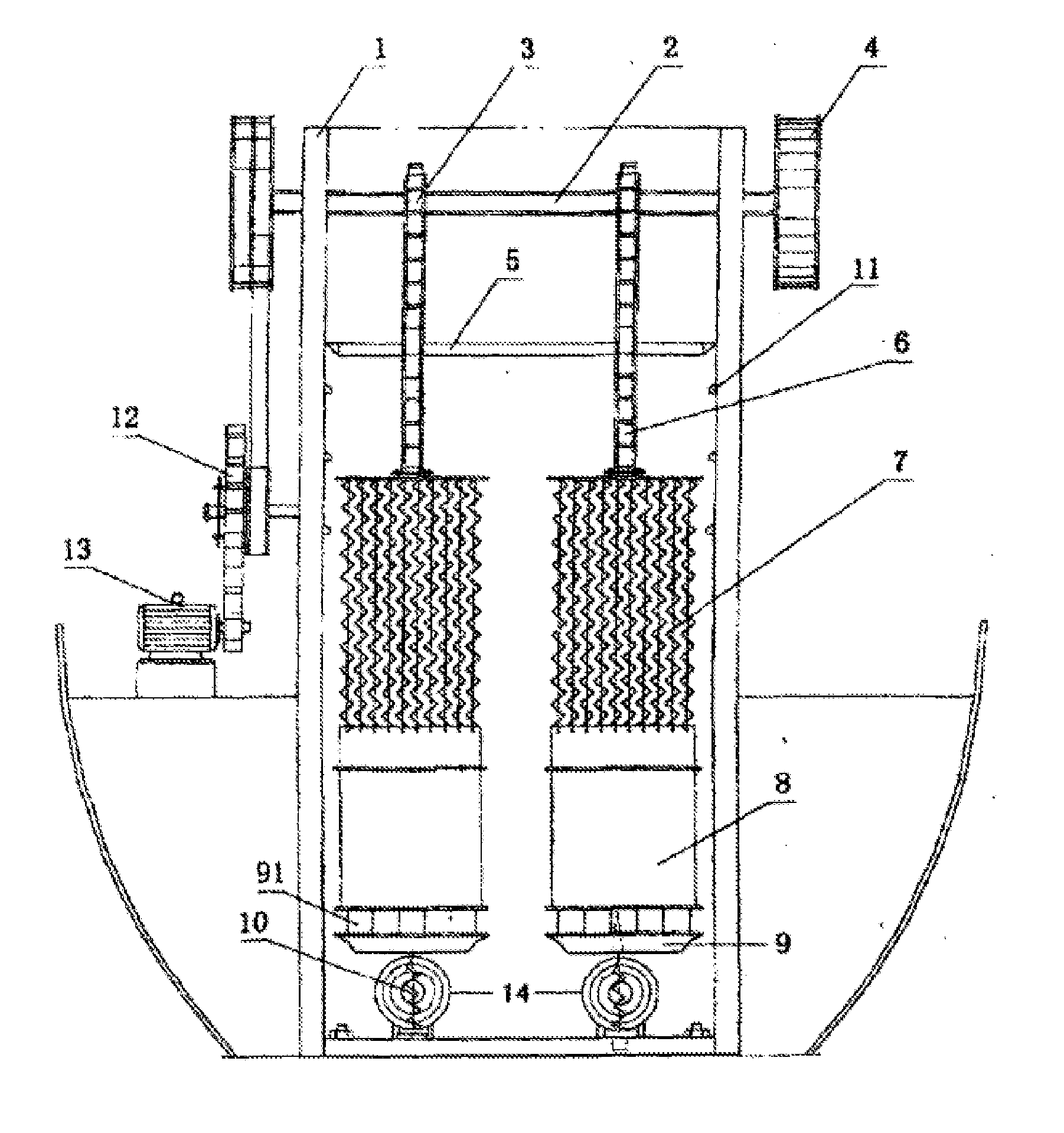
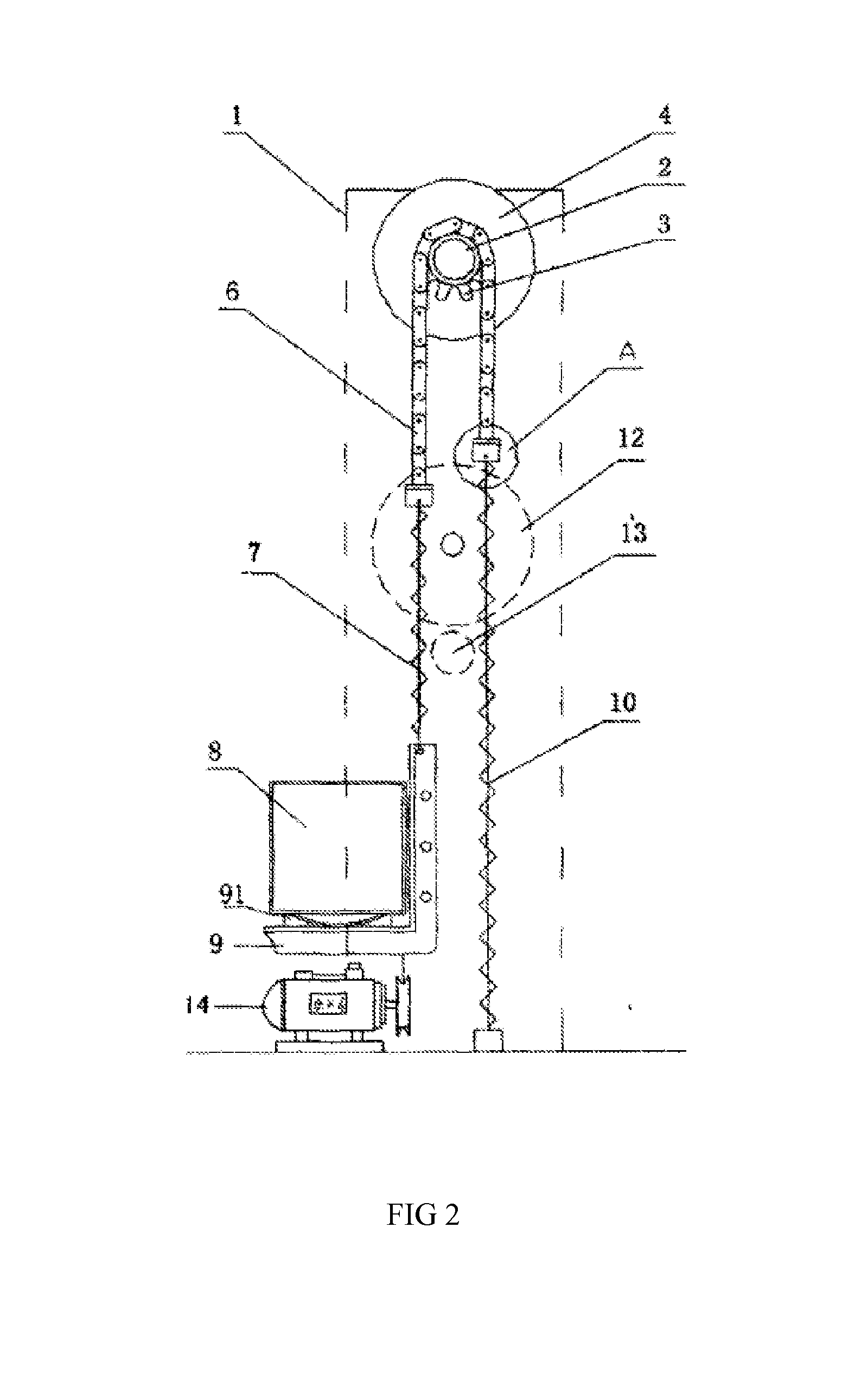
[0021]As shown in FIGS. 1, 2, and 3, an energy conversion device of the present invention comprises a device frame 1, a transmission shaft 2, ratchet wheels 3, flywheels 4, a limit latch 5, a chain 6, a combined spring 7, a weight 8, a luggage carrier 9, a return spring 10, and an energy feedback device 14.

[0022]The transmission shaft 2 is arranged on the device frame 1. Flywheels 4 are arranged at both ends of the transmission shaft 2. One or more of ratchet wheels 3 are arranged in parallel on the transmission shaft 2. The chain 6 is arranged on each of the ratchet wheels 3. One end of the chain 6 is fixed to the limit latch 5, and the other end is connected to one end of the combined spring 7. Three pairs of pawls 11 which match the limit latch are arranged on inner sidewalls of the device frame 1 in the same horizontal plane. Springs 111 are arr...


PUM


Abstract

The invention discloses a gravitational energy conversion device, comprises a device frame, a weight, a luggage carrier, a combined spring, a chain, a ratchet wheels, a transmission shaft, flywheels, a limit latch, and a return spring. The transmission shaft is arranged on the device frame. The flywheels are arranged at both ends of the transmission shaft. The ratchet wheels are arranged on the transmission shaft. The ratchet wheels engage with the chain. One end of the chain is fixed to the limit latch, and the other end is connected to one end of the combined spring. Pairs of pawls which match the limit latch are arranged on inner sidewalls of the device frame in the same horizontal plane. One end of the return spring is fixed to the limit latch, and the other end is fixed to the luggage carrier.

Description

CROSS-REFERENCE TO RELATED APPLICATION[0001]This application is the U.S. national phase of International Application No. PCT / CN2012 / 078723, filed on Jul. 16, 2012, which claims the priority benefit a Chinese Patent which is application No. 2011103726416 filed on Oct. 26, 2011. the entire contents of which is hereby incorporated by reference.BACKGROUND OF THE INVENTION[0002]1. Field of the Invention[0003]The present invention relates to an energy utilization device, and in particular to a gravitational energy conversion device which converts energy in a vibration of the combination of an object (under the action of gravitation / gravity) and an elastic element into mechanical energy, hydraulic energy, or pressure energy for later use.[0004]2. Background of Invention[0005]The energy issue, especially the use and development of green energy (such as wind, solar and tidal energy or the like) is currently not only prominent, but also difficult in terms of technical view. Among these, the w...

Claims


Application Information

Patent Timeline
IPC IPC(8): H02K7/18
CPCF03G1/00F03G3/00Y10S74/09H02K7/1807F03G7/10F03G7/104
Inventor XU, YULIANG
Owner XU YULIANG
Why Eureka
Try Eureka