Systems for heating a battery and processes thereof

a battery and process technology, applied in battery/fuel cell control arrangement, secondary cell servicing/maintenance, electrochemical generators, etc., can solve the problems of limited market penetration of evs, further adverse effects on the and greatly reduced driving range of evs. , to achieve the effect of extending the driving range of the vehicle and reducing the energy consumption of the battery

Inactive Publication Date: 2014-09-25
EC POWER LLC
View PDF15 Cites 88 Cited by
  • Summary
  • Abstract
  • Description
  • Claims
  • Application Information

AI Technical Summary

Benefits of technology

[0008]An advantage of the present invention is a battery system that can internally heat the battery of the system from below an optimum temperature, e.g., sub-operating temperature, to a higher temperature, e.g., about operating temperature, by using the heat generated through internal resistance of the battery itself. The battery system of the present disclosure can be included in an electric vehicle or plug-in hybrid electric vehicle and advantageously minimize battery energy consumption and extend the driving range of the vehicle in subfreezing environments.
[0009]These and other advantages are satisfied, at least in part, by a process of internally heating one or more batteries in a battery system. The process comprises: determining a first temperature of the battery or batteries; internally heating the one or more batteries by a pulse charging and discharging cycle between a first group of cells and a second group of cells within the battery or between two or more batteries if the first temperature is below a predetermined temperature (T1); and discontinuing the pulse charging and discharging cycle when the first temperature reaches a second predetermined temperature (T2).
[0010]Embodiments of the present disclosure include shuttling electrical energy between two or more groups of cells in a battery pack, wherein the pulse charging and discharging cycle is between a period of one tenth and a few tens seconds, wherein the one or more batteries are lithium ion batteries and a lower voltage level of power pulses is between about 0.5 and 3 V, and wherein the pulses can be constant current, constant voltage or constant or variable power. Additional embodiments include imposing a high frequency alternating current (AC) on a net non-zero mean DC current draw from a battery pack, and wherein the battery pack includes lithium ion batteries and a lower voltage level of AC pulses is between about 0.5 and 3V.
[0011]Another aspect of the present a battery system comprising a first cell group and a second cell group and an onboard controller for shuttling current between the first and second cell groups and sensing a first predetermined temperature and a second predetermined temperature of the first or second cell group.
[0012]Embodiments of the present disclosure include a DC-DC converter to shuttle DC pulse current between the two or more groups of cells; a switch in conjunction with the onboard controller for managing the amplitude and frequency of shuttling pulse current between the two or more group of cells; a voltage controlling device to maintain cell voltage at a pre-determined limit during shuttling pulse current between the two or more group of cells. Additional embodiments include a signal generating device to generate an AC signal with a pre-determined amplitude, frequency and wave form; a voltage controlling device to maintain cell voltage in a pre-determined limit during shuttling pulse current between the two or more group of cells.

Problems solved by technology

Despite offering the advantages of energy efficiency and low environmental impact, market penetration of EVs has been limited because of their relatively short driving range.
Furthermore, the driving range from EVs is greatly reduced in cold environments.
At subzero temperatures, the driving range of EV is further adversely affected due to the poor performance of the battery and due to the additional burden of the use of the battery to heat the cabin of the vehicle.
The poor performance of Li-ion batteries in EVs, for example, is closely related to significantly reduced energy and power capabilities of such batteries [2, 3], as well as capacity fade due to lithium plating upon charging [4, 5].
Fundamentally, the poor performance of Li-ion batteries at subzero temperatures arises from sluggish kinetics of charge transfer [6, 7], low electrolyte conductivity [8, 9] and reduced solid-state Li diffusivity [6, 10].
The poor performance of Li-ion cells at subzero temperatures implies significantly increased internal resistance.
However, a continuing need exists to ameliorate the reduced performance of rechargeable batteries subjected to cold temperatures.

Method used


Image

  • Systems for heating a battery and processes thereof
  • Systems for heating a battery and processes thereof
  • Systems for heating a battery and processes thereof

Examples


examples

[0036]The following examples are intended to further illustrate certain preferred embodiments of the invention and are not limiting in nature. Those skilled in the art will recognize, or be able to ascertain, using no more than routine experimentation, numerous equivalents to the specific substances and procedures described herein.

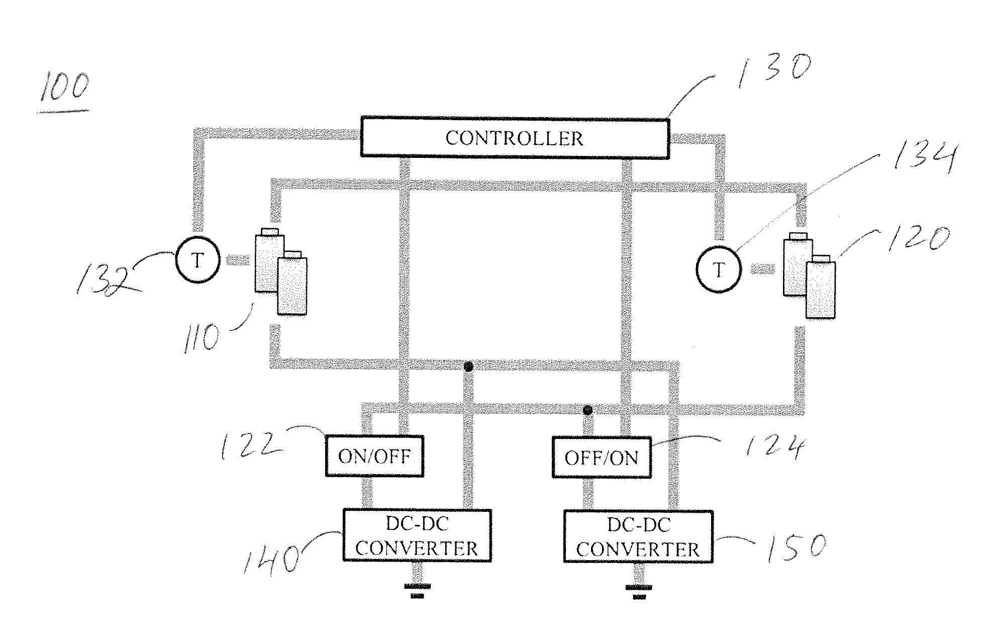
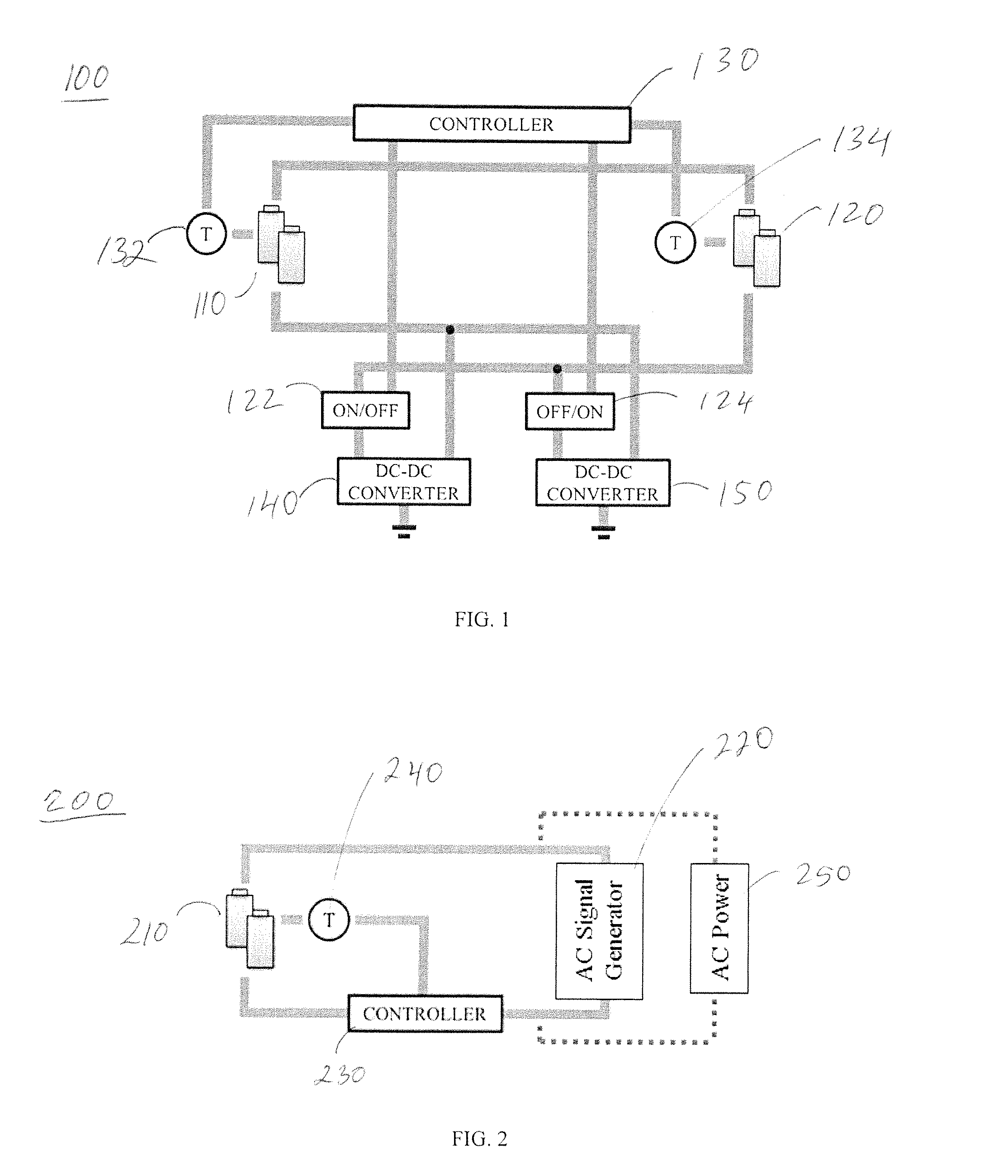
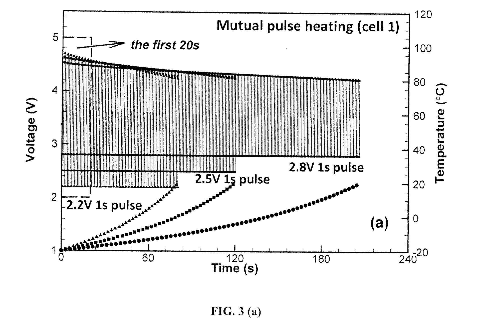
[0037]In the following example, a simulation is carried out for the mutual pulse heating cycle between two cells. For this simulation, two cells are connected using a dc-dc converter, as depicted in FIG. 1. The two cells start with the same initial conditions. The discharging cell is under a constant voltage mode. The voltage and temperature evolutions of cell 1 during the entire heating process are shown in FIG. 3(a). Discharge voltage levels of 2.2V, 2.5V and 2.8V are attempted independently. The lower levels of discharge voltage exhibit shorter heating time because of more heat generated internally. The pulse intervals are set to 1s. The voltage evoluti...


PUM


Abstract

A battery system is disclosed that can internally heat a battery by consuming minimal battery energy and with short heating times.

Description

CROSS-REFERENCE TO RELATED APPLICATION[0001]This application claims the benefit of U.S. Provisional Application No. 61 / 804,334 filed Mar. 22, 2013 the entire disclosure of which is hereby incorporated by reference herein.TECHNICAL FIELD[0002]The present invention relates generally to rechargeable electrochemical energy storage devices and processes for internally heating such devices from below an optimum temperature to a higher temperature. In particularly, the present disclosure is directed to rechargeable batteries that have efficient internal heating components and processes for internally heating such batteries.BACKGROUND[0003]Electric drive vehicles are a promising technology for reducing both greenhouse gas emissions and dependence on foreign oil. The market share for plug-in hybrid electric vehicles (PHEV) and pure electric vehicles (EVs) has increased significantly in recent years. Despite offering the advantages of energy efficiency and low environmental impact, market pen...

Claims


Application Information

Patent Timeline
Patent Type & Authority Applications(United States)
IPC IPC(8): B60L11/18H02J7/00
CPCB60L11/1875H02J7/0054H02J7/0052B60L1/02B60L2210/10B60L2240/545Y02T10/70H01M10/443H01M10/0525H01M10/425H01M2010/4271H01M10/615B60L50/16B60L58/12B60L58/22B60L58/25B60L58/27H02J7/00711H02J7/342H02J2310/48Y02E60/10Y02T10/72Y02T10/7072H02J7/0013H02J7/0047H02J7/007194
Inventor JI, YANWANG, CHAO-YANGSHAFFER, CHRISTIAN E.SINHA, PUNEET K.
Owner EC POWER LLC
Why Eureka
Try Eureka