Head-mounted display device and method of controlling head-mounted display device

a display device and display device technology, applied in static indicating devices, instruments, optical elements, etc., can solve the problems of difficult operation by eye movement, inability for users to visually recognize images,

Active Publication Date: 2014-09-25
SEIKO EPSON CORP
View PDF2 Cites 126 Cited by
  • Summary
  • Abstract
  • Description
  • Claims
  • Application Information

AI Technical Summary

Benefits of technology

[0013]An advantage of some aspects of the invention is to solve at least a part of the problems described above, and the invention can be implemented as the following aspects.

Problems solved by technology

Further, in the technology disclosed in Patent Document 2, when there is no flat surface within the predetermined distance from the user, it may be impossible for the user to visually recognize the image of the user interface, and there has been room for improvement in convenience.
Furthermore, in the head-mounted display device disclosed in Patent Document 6, the image to be visually recognized is set based on the eye movement of the user's eye, however, the operation by the eye movement may be difficult and the simpler operation method has been desired.

Method used


Image

  • Head-mounted display device and method of controlling head-mounted display device
  • Head-mounted display device and method of controlling head-mounted display device
  • Head-mounted display device and method of controlling head-mounted display device

Examples


first embodiment

A. FIRST EMBODIMENT

A-1. Configuration of Head-Mounted Display Device

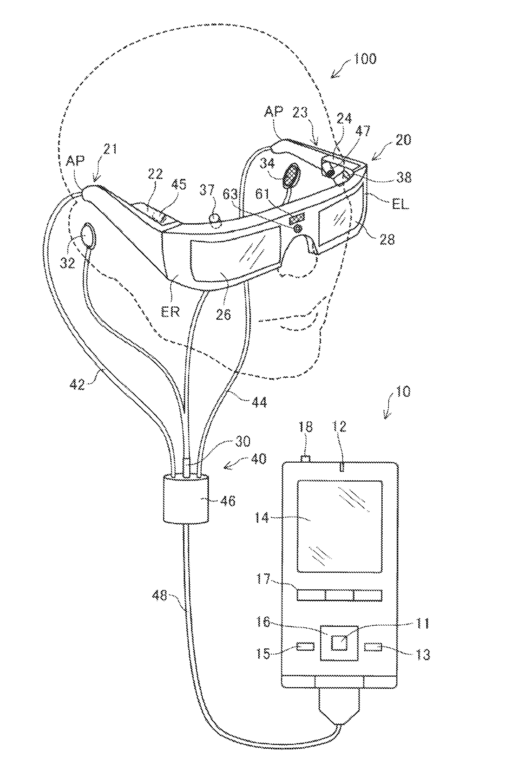
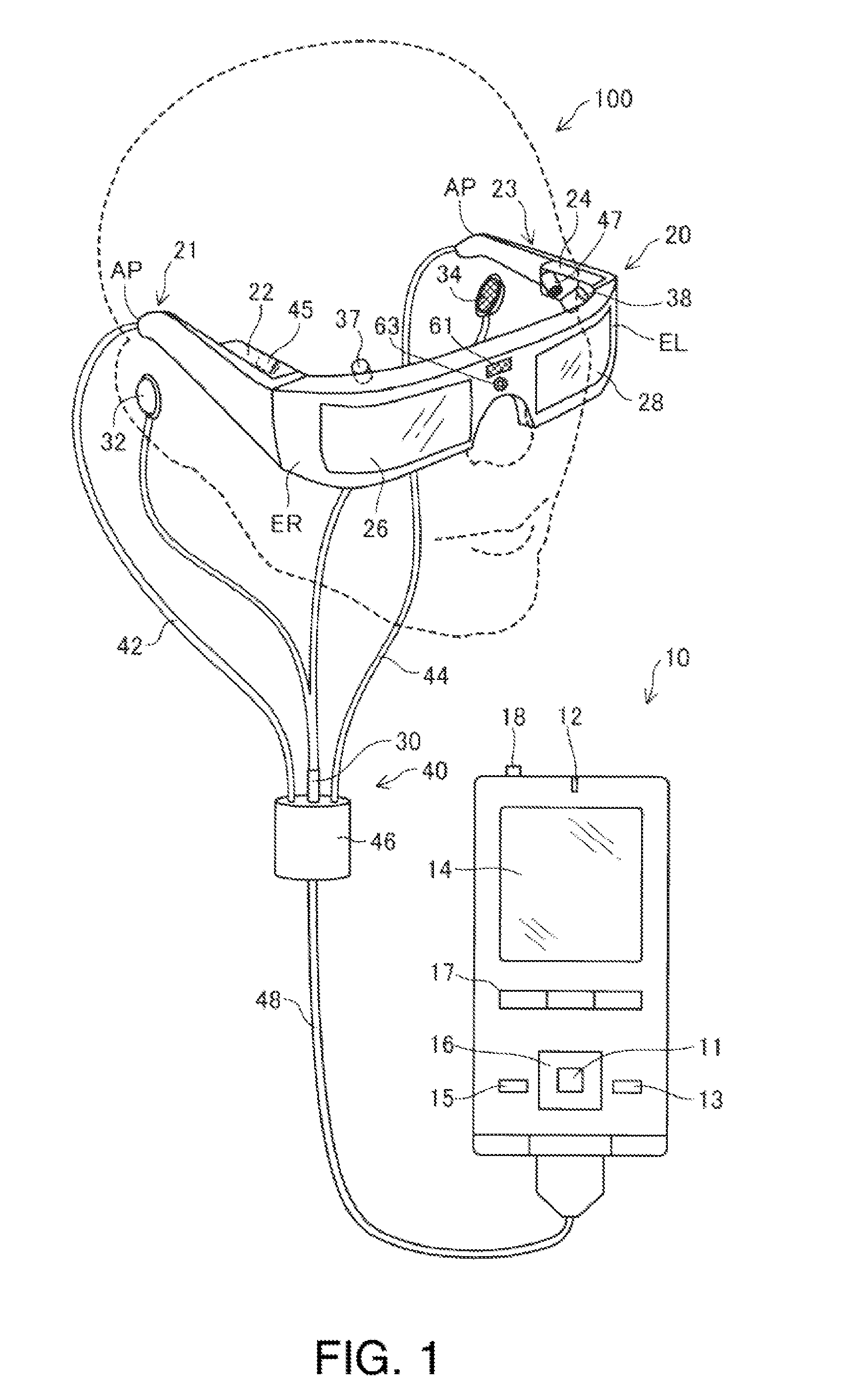
[0079]FIG. 1 is an explanatory diagram showing an outer configuration of a head-mounted display device 100. The head-mounted display device 100 is a display device worn on a head and also called a head-mounted display (HMD). The head-mounted display device 100 of the embodiment is an optically-transmissive head-mounted display device that enables visual recognition of a virtual image and direct visual recognition of outside scenery. Note that, in the specification, the virtual image visually recognized by the user using the head-mounted display device 100 is also referred to as “displayed image” for convenience. Further, output of image light generated based on image data is also referred to as “display of an image”.

[0080]The head-mounted display device 100 includes an image display unit 20 that is worn on a head of a user and allows the user to visually recognize a virtual image, and a control unit 10 (controller 1...

second embodiment

B. SECOND EMBODIMENT

[0126]FIG. 8 is an explanatory diagram showing an outer configuration of a head-mounted display device 100a in the second embodiment. In the second embodiment, compared to the first embodiment, the shape of an outside scenery imaging camera 61a is different and a track pad 36 is formed in an image display unit 20a. The outside scenery imaging camera 61a in the second embodiment is a monocular camera, however, may be a stereo camera. The angle of view of the outside scenery imaging camera 61a used in the second embodiment is 40 degrees respectively in the vertical directions and 60 degrees respectively in the horizontal directions from the start point of the optical axis.

[0127]The track pad 36 detects finger operation of the user on the operation surface of the track pad 36, and outputs a signal in response to the detection. When the user wears the image display unit 20a on the head, the track pad 36 is located on the surface opposite to the temporal part of the u...

third embodiment

C. THIRD EMBODIMENT

[0152]The third embodiment is different from the above described embodiments in the method of specifying the line-of-sight direction. When fixating a point of fixation as a specific point, the user does not fixate actually only one point of the point of fixation, but fixates a predetermined range around the point of fixation. As described above, the fine wobbling of eyes that involuntarily and constantly occurs even when a human intends to fixate a point of fixation is called involuntary eye movement. In the third embodiment, in the involuntary eye movement, the line-of-sight directions are specified based on the distances of the eye wobbling from the point of fixation within a predetermined time, the frequency specification of the eye wobbling, or the like.

[0153]In the third embodiment, the image determination part 142 specifies the line-of-sight direction of the user and determines whether or not the user fixates the point of fixation by analyzing the eye wobbli...


PUM


Abstract

A transmissive head-mounted display device includes an image display unit that generates image light representing an image, allows a user to visually recognize the image light, and transmits outside scenery when worn on a head of a user, a detection unit that detects at least one of a line-of-sight direction of the user and a shielding object that is located at a predetermined distance from an eye of the user and shields a line of sight of the user, and a control unit that performs control of the image light based on the detected detection result.

Description

BACKGROUND[0001]1. Technical Field[0002]The present invention relates to a head-mounted display device.[0003]2. Related Art[0004]Head-mounted display devices (head-mounted displays, HMDs) as display devices worn on heads have been known. For example, the head-mounted display device generates image light representing an image using a liquid crystal display and a light source, guides the generated image light to an eye of a user using a projection system and a light guide plate, and thereby, allows the user to visually recognize a virtual image. There are two types of head-mounted display devices of a transmissive type that enables the user to visually recognize outside scenery in addition to the virtual image and a non-transmissive type that disables the user to visually recognize the outside scenery. The transmissive head-mounted display devices include an optical transmissive type and a video transmissive type. As input devices for operation of the head-mounted display device, for ...

Claims


Application Information

Patent Timeline
Patent Type & Authority Applications(United States)
IPC IPC(8): G02B27/01H04M1/72412
CPCG02B27/017G06F3/005G06F3/012G06F3/017G06F3/0304G02B27/0093G02B2027/0187G02B2027/0178G02B2027/014H04M1/05G06F3/013H04M1/724097H04M1/72412G02B27/0172G06F3/04812G06F3/0482
Inventor TAKANO, MASAHIDEKIMURA, FUSASHI
Owner SEIKO EPSON CORP
Why Eureka
Try Eureka