Method and apparatus for automatic camera calibration using one or more images of a checkerboard pattern

a technology of automatic camera calibration and checkerboard pattern, which is applied in the field of automatic camera calibration using one or more images of checkerboard pattern, can solve the problems of comprehensive degrading the accuracy of real image measurements, introducing aberrations in the resulting images, and affecting the quality of the imag

Active Publication Date: 2014-09-25
UNIVE DE COIMBRA
View PDF6 Cites 74 Cited by
  • Summary
  • Abstract
  • Description
  • Claims
  • Application Information

AI Technical Summary

Benefits of technology

[0013]The solution provided herein relies on a complete geometric calibration of optical devices, such as cameras commonly used in medicine and in industry in general, and subsequent rendering of perspective correct image in real-time. The calibration consists on the determination of the parameters of a suitable mapping function that assigns each pixel to the 3D direction of the correspondi...

Problems solved by technology

The departure of practical optical systems from ideal behavior leads to the introduction of aberrations in the resulting images.
The aberration here is lens distortion, which is present in both color and grey-scale imaging devices.
It comprehensively degrades the accuracy of measurements made in real images, where pixels in a normal perspective camera can suffer large displacements along the radial directions.
An intrinsic problem for “plumb line” based calibration is that the optimization/search must be run with respect to both the straight line parameters (that are unknown) and the distortion parameters (that are also unknown).
No sufficiently validated mathematical relationship exists between the objective error and the distortion parameters, hence no analytical derivatives are available.
These results in slow conve...

Method used


Image

  • Method and apparatus for automatic camera calibration using one or more images of a checkerboard pattern
  • Method and apparatus for automatic camera calibration using one or more images of a checkerboard pattern
  • Method and apparatus for automatic camera calibration using one or more images of a checkerboard pattern

Examples


Embodiment Construction

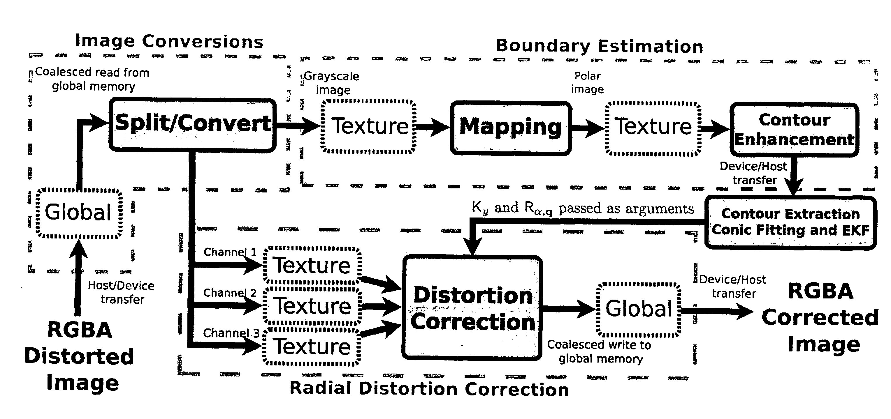
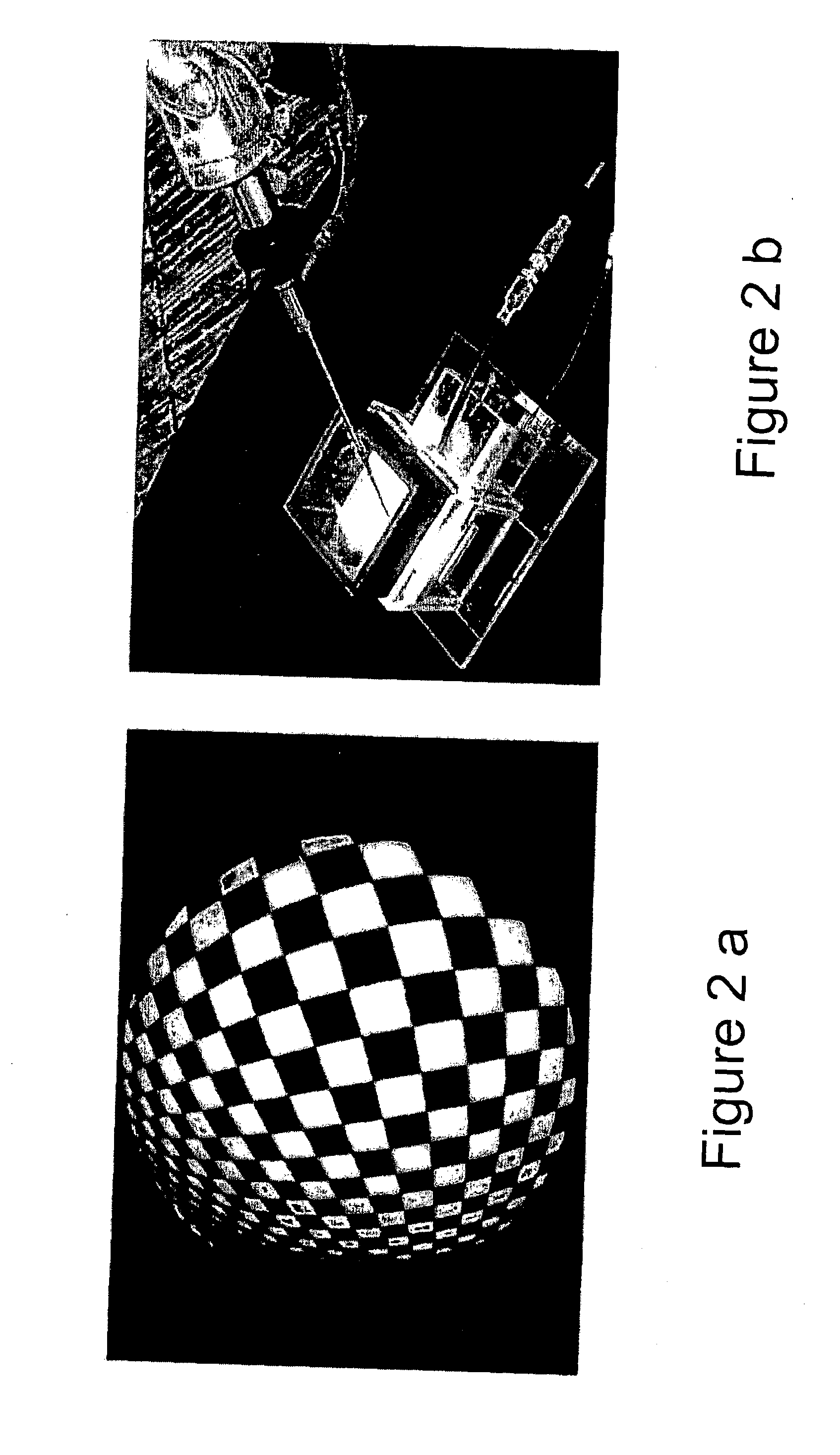
[0031]We propose a complete solution for the calibration, online updating of the projection parameters in case of lens rotation, and radial distortion correction in real-time. The solution comprises the modules and blocks shown in the scheme in FIG. 3 and the apparatus of FIG. 14, being that the operator starts by acquiring a single image of a checkerboard pattern using the setup in FIG. 2.

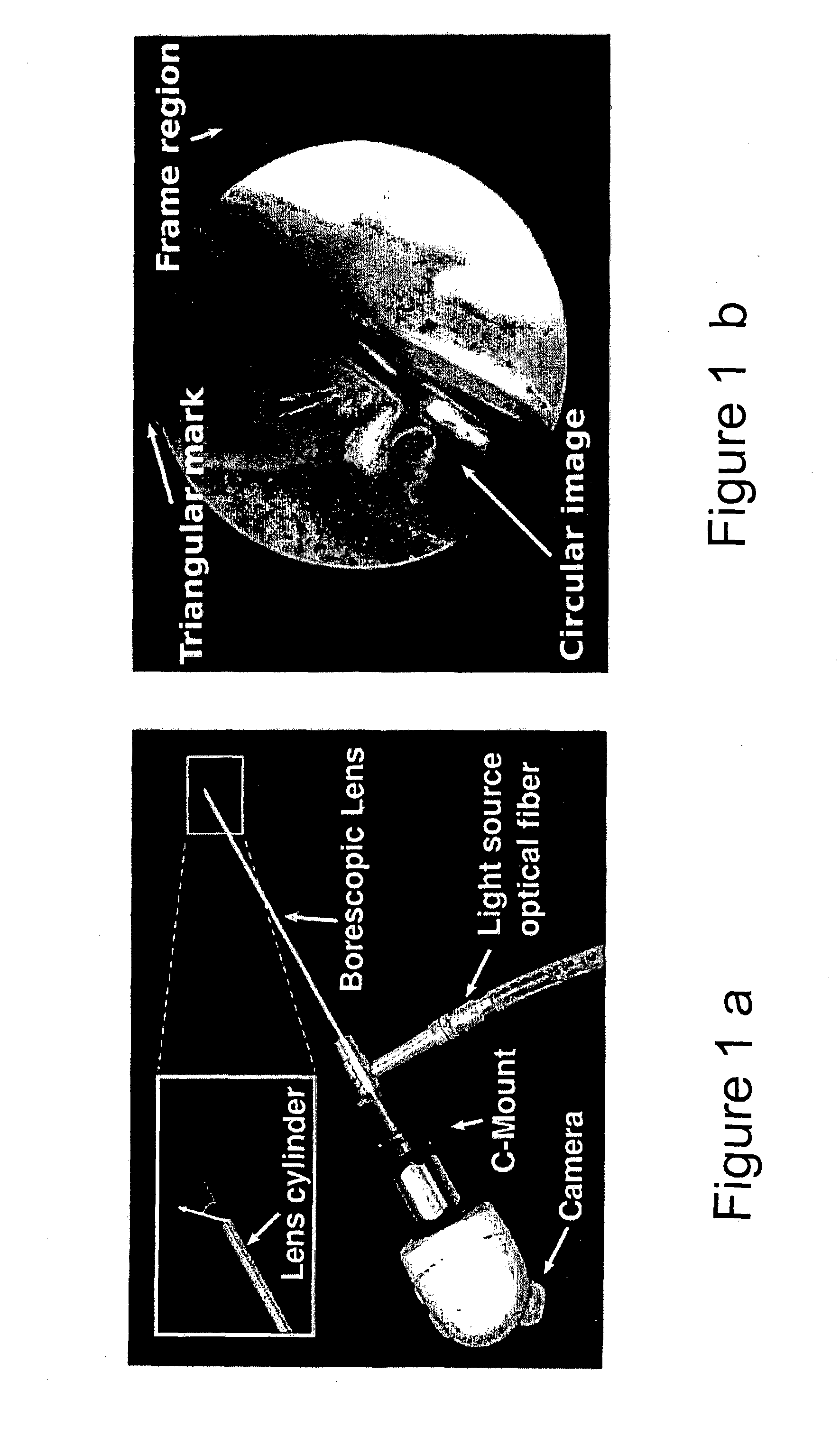
[0032]The system herein presented was originally meant for medical endoscopy that typically employs a boroscopic lens probe mounted on a standard CCD camera. However, our solution is extendable to other application domains using cameras with significant radial distortion that might benefit from accurate geometric calibration and real-time image correction. Examples of these domains include surveillance, industrial inspection, automotive, robot navigation, etc, that often rely in images / video acquired by cameras equipped fish-eye lenses, wide angular lenses, mini lenses, or low quality optics.

[0033...


PUM


Abstract

The present invention relates to a high precision method, model and apparatus for calibrating, determining the rotation of the lens scope around its symmetry axis, updating the projection model accordingly, and correcting the image radial distortion in real-time using parallel processing for best image quality.
The solution provided herein relies on a complete geometric calibration of optical devices, such as cameras commonly used in medicine and in industry in general, and subsequent rendering of perspective correct image in real-time. The calibration consists on the determination of the parameters of a suitable mapping function that assigns each pixel to the 3D direction of the corresponding incident light. The practical implementation of such solution is very straightforward, requiring the camera to capture only a single view of a readily available calibration target, that may be assembled inside a specially designed calibration apparatus, and a computer implemented processing pipeline that runs in real time using the parallel execution capabilities of the computational platform.

Description

CROSS REFERENCE TO RELATED APPLICATIONS[0001]This application is a 371 application of International Application No. PCT / PT2012 / 000030, filed Jul. 25, 2012, which claims priority to Portuguese Patent Application PT105832, filed Jul. 25, 2011, all of which are incorporated by reference in its entirety herein.FIELD OF INVENTION[0002]The present invention relates to a high precision method, model and apparatus for calibrating, determining the rotation of the lens scope around its symmetry axis, updating the projection model accordingly, and correcting the image radial distortion in real-time using parallel processing for best image quality.BACKGROUND OF THE INVENTION[0003]An optical instrument is generally required to produce a geometrically consistent image of a given object, where each point in 3D is projected into a point in the image. The image is generally formed in accordance with some predefined imaging model, which in this case, it is assumed to be a pin-hole model. The departur...

Claims


Application Information

Patent Timeline
IPC IPC(8): H04N17/00H04N5/232
CPCH04N5/23293H04N17/002A61B1/00057G06T2207/30208G06T7/80H04N23/555H04N23/63
Inventor BARRETO, JOAO PEDRO DE ALMEIDAFERNANDES, GABRIEL FALCAO PAIVATEIXEIRA, RUI JORGE MELO
Owner UNIVE DE COIMBRA
Why Eureka
Try Eureka