Laser device with kerr effect based mode-locking and operation thereof

a laser device and kerr lens technology, applied in the direction of laser details, optical resonator shape and construction, electrical apparatus, etc., can solve the problems of reduced gain bandwidth, reduced gain bandwidth, and reduced gain bandwidth, so as to achieve compact resonator design and easy independent adjustment

Active Publication Date: 2014-09-25
MAX PLANCK GESELLSCHAFT ZUR FOERDERUNG DER WISSENSCHAFTEN EV +1
View PDF4 Cites 28 Cited by
  • Summary
  • Abstract
  • Description
  • Claims
  • Application Information

AI Technical Summary

Benefits of technology

[0044]As a further particular advantage of the invention, the first mode shaping section allows a new design of the second mode shaping section adjusting the beam waist in the Kerr medium. Thus, according to a preferred embodiment of the invention, the second mode shaping section comprises the first group of resonator mirrors including at least two curved resonator mirror, which form a telescope. The second mode shaping section is a telescopic section imaging the circulating electric field into the Kerr medium. According to particularly preferred embodiments of the invention, the telescope section may comprise two concave mirrors or one concave and one convex mirror. In particular, a Newtonian or a Galilean telescope can be provided by the second mode shaping section. The telescope arrangement can be symmetric, i.e. the curved mirrors can have the same radii of curvature, or asymmetric, i.e. the curved mirrors have different radii of curvature. Furthermore, the telescope section can have different arm lengths and a distance between the mirrors spanning the telescope section which is selected depending on the resonator stability. As a further alternative, the second mode shaping section may comprise two concave resonator mirrors.
[0045]As a further advantage of the invention, the beam waist scaling arrangement (second mode shaping section) can be implemented in any thin disc resonator design. Depending on the cavity sensitivity to the Kerr effect and optional measures for influencing the Kerr effect, the second mode shaping section can be implemented in any cavity point. Thus, according to a further preferred embodiment of the invention, the Kerr medium can be arranged in the second mode shaping section, i.e. between the curved mirrors spanning the telescopic section or as an end mirror of the second mode shaping section. As an advantage, multiple degrees of freedom for adjusting the Kerr medium relative to the light path in the laser resonator can be obtained. Alternatively, the Kerr medium can be arranged outside of the second mode shaping section, in particular on a side of the telescope section opposite to the arrangement of the first mode shaping section within the laser resonator.
[0046]Furthermore, the arrangement of the first and second mode shaping sections relative to each other can be selected. With a first variant, the first and second mode shaping sections are arranged adjacent to each other along the light path in the laser resonator. Advantageously, this embodiment of the invention allows an easy independent adjustment of the beam sizes in the Kerr medium and the gain disc medium, respectively. According to a second variant, the second mode shaping section can be included in the first mode shaping section. As an advantage, this embodiment of the invention can provide a particularly compact resonator design.
[0047]The mode-locking Kerr medium generally comprises a solid optical element made of an optically non-linear material being capable of showing the Kerr effect. According to a preferred variant, the Kerr medium comprises a Kerr lens optical plate, which is arranged e.g. in a free-standing fashion in the optical path of the laser resonator. Advantageously, the free-standing plate can be freely adjusted relative to the light path. Alternatively, the Kerr medium may comprise a Kerr lens mirror, which is arranged as a folding mirror in the laser resonator. In this case, advantages in terms of avoiding thermal lensing effects can be obtained. In particular, the Kerr lens mirror can be provided in contact with a substrate, which forms a heat sink. Preferably, a bulky substrate with or without cooling, e.g. water cooling or electrical cooling, is used. On the substrate, the Kerr lens mirror comprises a reflective layer carrying the Kerr effect material. The Kerr lens mirror can be wedge-shaped or can have a plane-parallel shape, and / or it can be provided without or with an anti-reflective coating on the Kerr effect material.
[0048]As Kerr effect material, any available optically non-linear material showing the Kerr effect can be used. As a further advantage, in particular in combination with the combined use with a SESAM, the Kerr medium may comprise CaF2, fused silica, sapphire or optical glass, like e.g. SF57 (tradename). Preferably, the optical path length of the Kerr medium along the laser resonator is below 6 mm, in particular below 1 mm. The optical path length practically used can be selected in dependency on the material of the Kerr medium.
[0049]According to a further preferred embodiment of the invention, the laser resonator can be provided with a semiconductor saturable absorber mirror (SESAM). According to this embodiment, the laser pulses are created using mode-locking with both of the Kerr medium and the SESAM. Advantageously, the SESAM can be used as a starter for the mode-locking operation. Preferably, the SESAM is arranged at an end of the laser resonator adjacent to the second mode shaping section and opposite relative to the first mode shaping section.

Problems solved by technology

However, in prior art it has been emphasized that pulse duration from Yb:YAG thin disk lasers is limited to about 700 fs [3, 6].
In [6] this limitation is related to the higher saturated gain and the reduced gain bandwidth due to a high inversion level at high power operation.
Moreover, Kerr lens mode locking includes very complex self focusing dynamics as well as complex cavity design.
The complexity is caused by the analysis of the cavity behaviour near the stability edges which is necessary for reliable initiation of Kerr lens mode locking.
Therefore cavity design and initiation of mode locking is much more complex task here compared with the dye laser techniques.
On the other hand, SESAMs have a number of drawbacks relating to Q-switching instabilities, low damage threshold, two photon absorption, thermal lensing resulting from saturable and non-saturable losses, finite relaxation time and limited supported bandwidth.
Therefore the damage threshold of the SESAM sets a limitation in maximum achievable pulse energies and minimum achievable pulse durations inside the laser cavity.
Furthermore, thermal lensing limits the average achievable power from the oscillator.
Damage of the SESAM can also be partially caused by the heating of the device.
However, both the thin disk pumped at high average power and the SESAM having saturable and non-saturable losses exhibit thermal lensing effects.
Moreover enlarging the beam size in the cavity leads to shrinking of the stability zones.
These features introduce more restrictions and make designing the cavity a more complex task.
Evidently, including a second thermal lens (SESAM) in a cavity will make designing the cavity for fundamental mode operation even more complicated and narrow the stability zones even further.
Due to the following disadvantages and restrictions, the resonator design of FIG. 13 is barely applicable in practice.
Typically small beam sizes inside the cavity lead to the high risk of damaging of optical components.
But until now no thin disk laser generating emission-bandwidth-limited pulses or even beyond the emission-bandwidth-limit at high power level has been realized yet.
However, the telescopic geometry and the concave-convex geometry have not yet been used in the field of mode-locked thin disk laser resonators.

Method used


Image

  • Laser device with kerr effect based mode-locking and operation thereof
  • Laser device with kerr effect based mode-locking and operation thereof
  • Laser device with kerr effect based mode-locking and operation thereof

Examples


Embodiment Construction

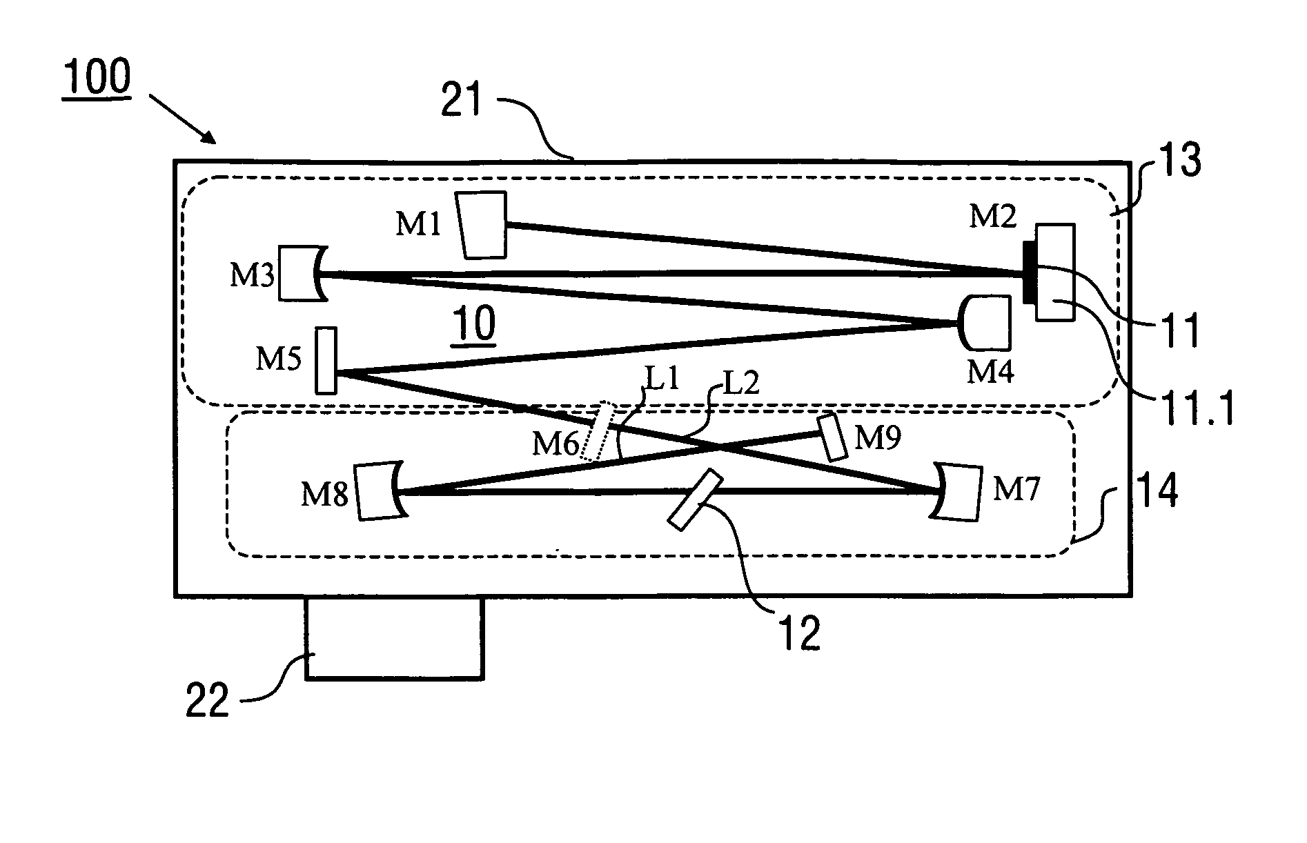
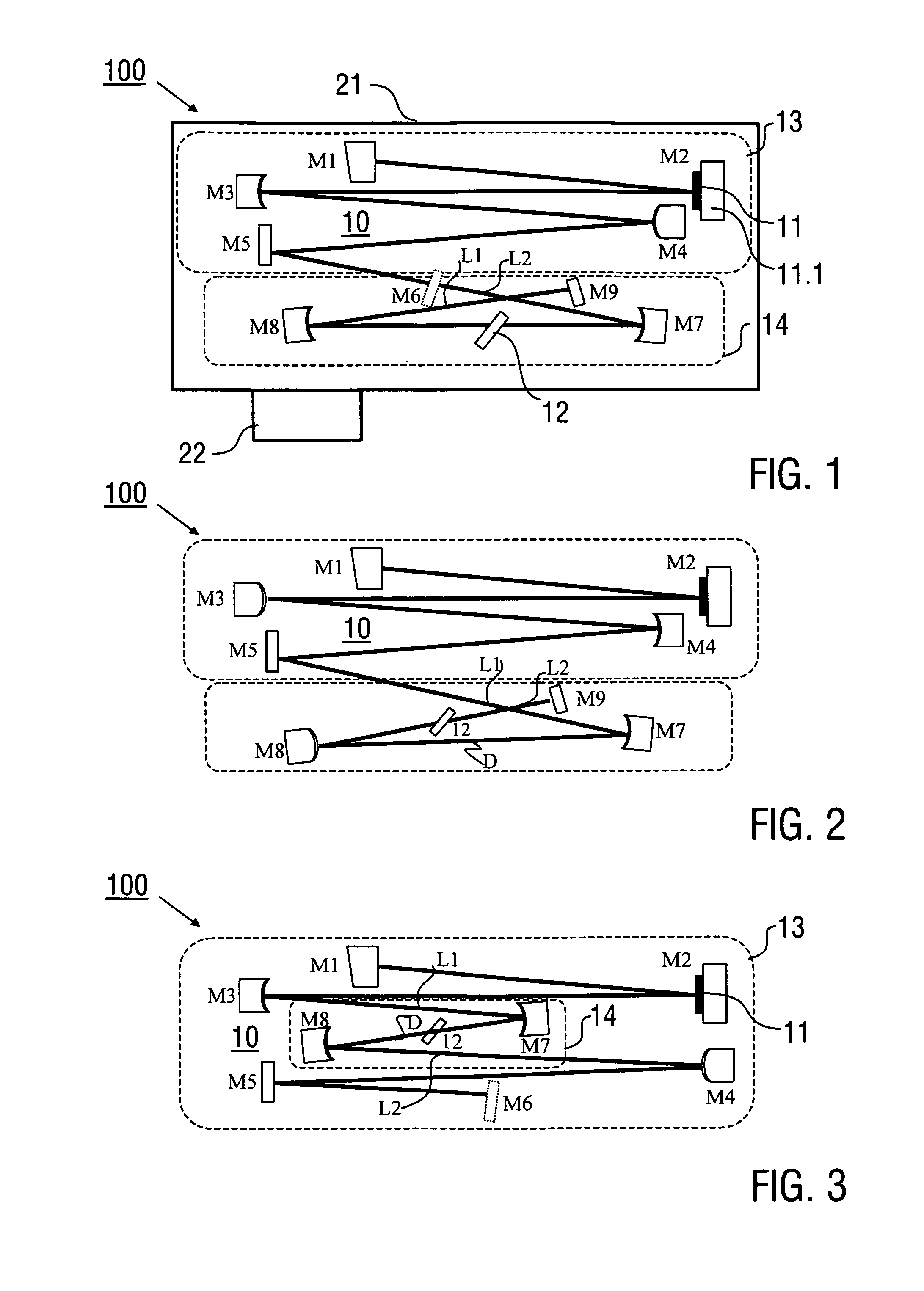
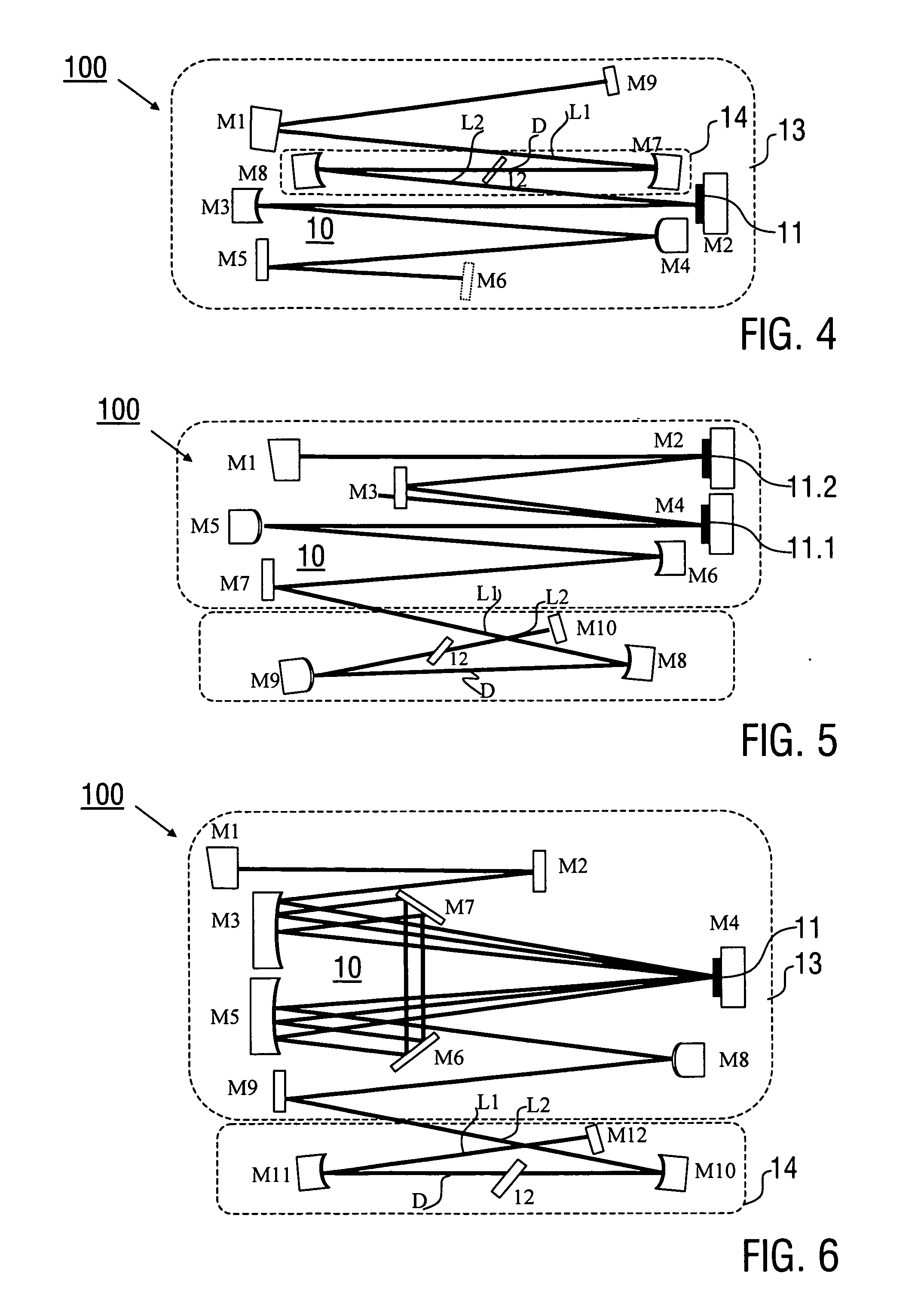
[0067]Preferred embodiments of the invention are described in the following with particular reference to the design of the laser resonator, in particular the first and second mode shaping sections. Details of the optical components of the laser resonator, in particular the design of the reflective mirrors, the gain disc medium, the Kerr medium, a hard aperture and the optional SESAM are not described as far as they can be implemented as in conventional techniques. In particular, the techniques of pumping the gain disc medium are not described as they are known as such in prior art (see e.g. [1]). It is emphasized that the implementation of the invention is not restricted to the illustrated resonator geometries, but rather possible with any other types of laser resonators including at least one gain disc medium.

[0068]FIG. 1 illustrates a first embodiment of an inventive laser device 100 with a laser resonator 10 including multiple resonator mirrors M1-M5 and M7-M9, wherein the mirror...


PUM


Abstract

A laser device (100), configured for generating laser pulses, has a laser resonator (10) with a gain disk medium (11) and a Kerr medium (12). The laser resonator (10) includes a first mode shaping section (13) which is adapted for shaping a circulating electric field coupled into the gain disk medium (11), and a second mode shaping section (14), which is adapted for shaping the circulating electric field coupled into the Kerr medium (12) independently of the electric field shaping in the first mode shaping section (13). Furthermore, a method of generating laser pulses (1) using a laser resonator (10) with a gain disk medium (11) and a Kerr medium (12) is described.

Description

FIELD OF THE INVENTION[0001]The present invention relates to a laser device, which is configured for generating laser pulses, in particular to a femtosecond laser device including a gain disc medium and a mode-locking Kerr medium in a laser resonator. Furthermore, the invention relates to a method of generating laser pulses with a laser device, in particular generating femtosecond laser pulses using a laser resonator, which includes a gain disc medium and a mode-locking Kerr medium. Applications of the invention are present in the fields of laser technique, in particular in the fields of operating laser devices for measuring purposes, for material processing or as excitation sources for creating UV-, XUV- or X-radiation. Preferred applications of the invention are available e.g. in the field of operating high-power ultra-fast laser sources.BACKGROUND OF THE INVENTION[0002]In the present specification, reference is made to the following prior art of conventional pulse laser devices.[...

Claims


Application Information

Patent Timeline
Patent Type & Authority Applications(United States)
IPC IPC(8): H01S3/08
CPCH01S3/08018H01S3/0805H01S3/0811H01S3/0813H01S3/108H01S3/1112H01S3/1118H01S3/1618H01S3/027H01S3/0604H01S3/1643
Inventor PRONIN, OLEGKRAUSZ, FERENCAPOLONSKIY, ALEXANDERBRONS, JONATHAN
Owner MAX PLANCK GESELLSCHAFT ZUR FOERDERUNG DER WISSENSCHAFTEN EV
Why Eureka
Try Eureka