Percutaneous cable with redundant conductors for implantable blood pump

a technology of percutaneous cable and conductor, which is applied in the direction of circulatory assistance devices, intravenous devices, therapy, etc., can solve the problems of reducing the expected time-to-failure of the remaining good conductor, affecting the expected time-to-failure, so as to shorten the expected time-to-failure

Active Publication Date: 2014-09-25
TC1 LLC
View PDF10 Cites 12 Cited by
  • Summary
  • Abstract
  • Description
  • Claims
  • Application Information

AI Technical Summary

Benefits of technology

[0009]It has been discovered that the conventional approach of placing the redundant conductors adjacent to one another can lead to premature failure of the redundancy. In a typical failure mode, flexing of the cable may lead to a cracking or tearing along a particular edge of the cable which penetrates one of the condu

Problems solved by technology

It has been discovered that the conventional approach of placing the redundant conductors adjacent to one another can lead to premature failure of the redundancy.
In a typical failure mode, flexing of the cable may lead to a cracking or tearing along a particula

Method used


Image

  • Percutaneous cable with redundant conductors for implantable blood pump
  • Percutaneous cable with redundant conductors for implantable blood pump
  • Percutaneous cable with redundant conductors for implantable blood pump

Examples


Embodiment Construction

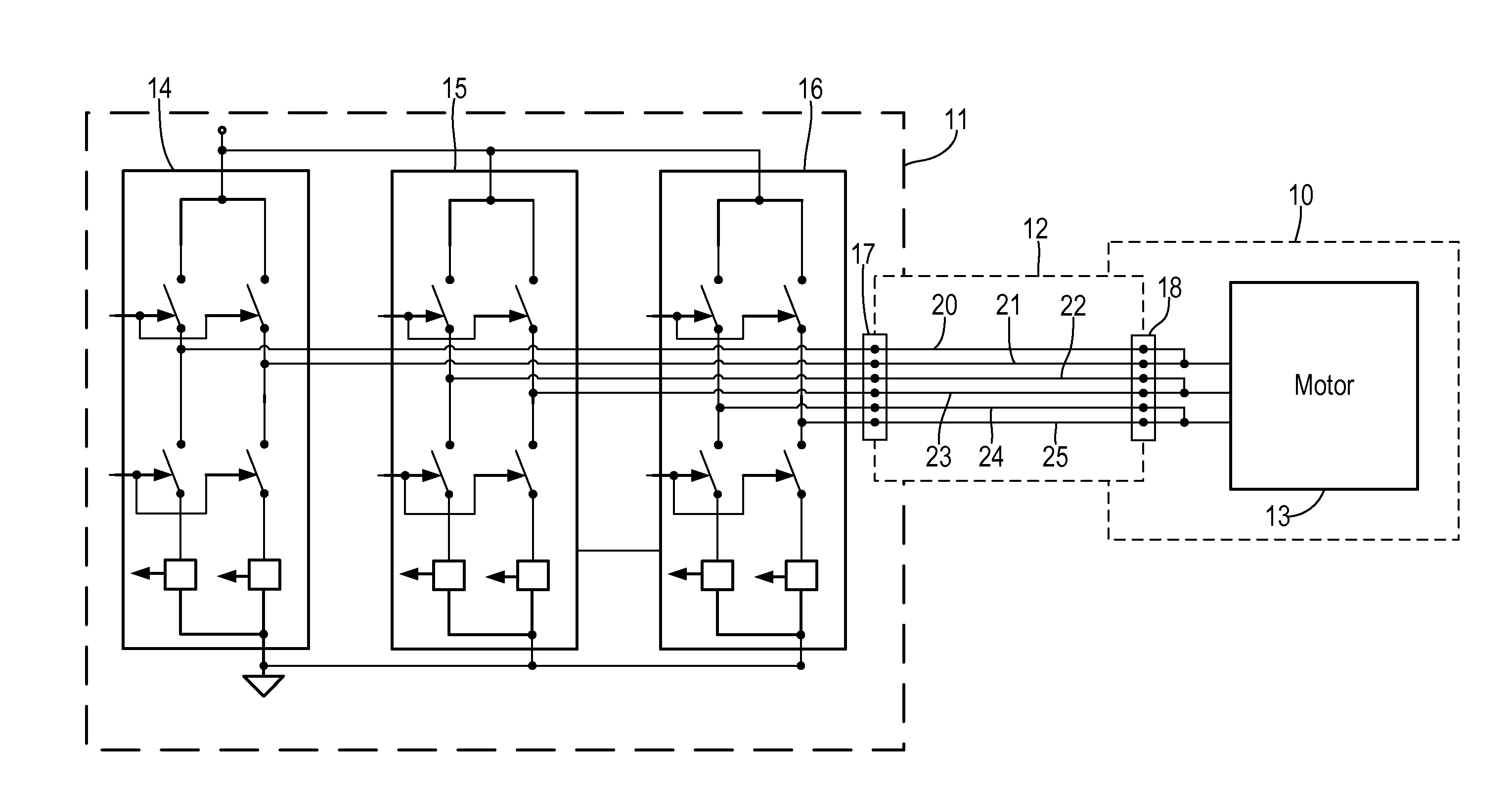
[0016]FIG. 1 shows a ventricular assist system in which a pump unit 10 is driven by an inverter 11 in an external control unit. A percutaneous cable 12 couples inverter 11 to a motor 13 in pump unit 10. Inverter 11 has a first phase 14, a second phase 15, and a third phase 16. Each phase has a pair of redundant phase legs with respective upper and lower power switches. Each phase leg is connected to a respective terminal on a terminal block 17. Cable 12 includes conductors 20-25 connected between terminal block 17 and a terminal block 18 in pump unit 10. Conductors 20 and 21 redundantly carry the drive signals for phase 14, conductors 22 and 23 redundantly carry the drive signals for phase 15, and conductors 24 and 25 redundantly carry the drive signals for phase 16. The redundant drive signals are joined in pump unit 10 and are coupled to motor 13 in order to drive respective motor windings.

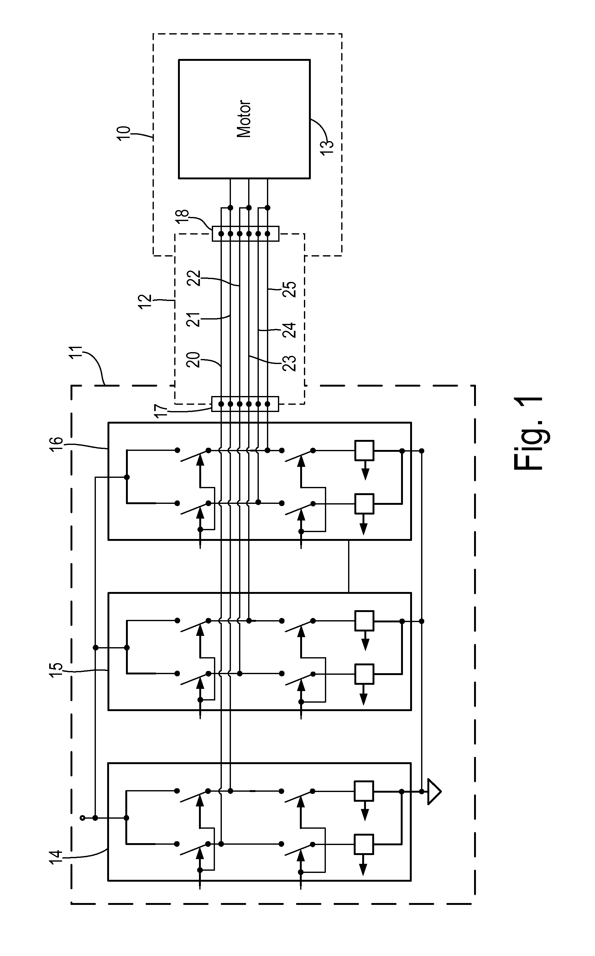
[0017]Referring to FIG. 2, a percutaneous cable 20 is shown in radial cross-section having s...


PUM


Abstract

A blood pump system for left ventricle assist has an implantable pump unit having a multiphase stator having a plurality of windings connected between respective junctions for forming first, second, and third phases. An external control unit comprises an H-bridge inverter having first, second, and third phase legs. A percutaneous cable is provided having first, second, and third parallel pairs of redundant conductors. Each conductor pair is connected between a respective phase leg and a respective junction. The conductors are arranged concentrically around a cable core so that individual conductors of each pair are separated by at least one conductor of a different conductor pair.

Description

CROSS REFERENCE TO RELATED APPLICATIONS[0001]Not Applicable.STATEMENT REGARDING FEDERALLY SPONSORED RESEARCH[0002]Not Applicable.BACKGROUND OF THE INVENTION[0003]The present invention relates in general to circulatory assist devices, and, more specifically, to enhanced reliability of a cable connection between an external control unit and an implanted pump unit.[0004]Many types of circulatory assist devices are available for either short term or long term support for patients having cardiovascular disease. For example, a heart pump system known as a left ventricular assist device (LVAD) can provide long term patient support with an implantable pump associated with an externally-worn pump control unit and batteries. The LVAD improves circulation throughout the body by assisting the left side of the heart in pumping blood. One such system is the DuraHeart® LVAS system made by Terumo Heart, Inc., of Ann Arbor, Mich. The DuraHeart® system employs a centrifugal pump with a magnetically l...

Claims


Application Information

Patent Timeline
IPC IPC(8): A61M1/12
CPCA61M1/122A61M60/88A61M60/178A61M60/216A61M60/411A61M60/148
Inventor YANAI, MASAMICHIBHATT, HIMANSHU K.
Owner TC1 LLC
Why Eureka
Try Eureka