Tamper-resistant RFID disabling apparatus

a technology of rfid and disabling apparatus, which is applied in the direction of identification means, instruments, computing, etc., can solve the problems of excessive band, creases in the band, and inconvenience of wearers, so as to reduce the cost of the band, reduce the design complexity of the band, and reduce the effect of the adhesive in reattaching the bond

Inactive Publication Date: 2006-09-14
BARTRONICS HONG KONG
View PDF39 Cites 23 Cited by
  • Summary
  • Abstract
  • Description
  • Claims
  • Application Information

AI Technical Summary

Benefits of technology

[0005] Although cutting extra tail piece has become the custom, others have tried to create an adhesive region at the end of the excess band that can then be used to adhere the end of the excess band back to the band itself. However, there are several drawbacks to this approach, such as cost of the band, design complexity of the band, and adhesion of the adhesive bond over time. That is, adhesives tend to become weaker over time with exposure to the elements and physical stress. Therefore, the adhesive bond is likely to fail in active environments such as resorts, water parks, concerts, and other entertainment venues where such bracelets would likely be used. If the bond should come apart, the efficacy of the adhesive in reattaching the bond is drastically reduced.
[0006] Others have also attempted to fold back the additional tail piece and reattach it to the band. This is sometimes done with non-RFID bracelets under circumstances where scissors are not available, even though no circuitry is attached to the bracelet. Commonly, this is done by attaching the excess band back to the band through the single-use locking mechanism. This has two primary drawbacks. First, folding back the excess band leaves a loop of material protruding from the bracelet. This may be less of a nuisance for the wearer, but still can interfere with the wearer's movement and comfort. Second, folding back the excess band creates a region where the probability of a crease becoming formed in the band is greatly increased. Consequently, the tamper wire that runs past this fold is exposed to more stress than circuitry in other areas of the band. As such, folding the excess band back for reattachment makes the apparatus vulnerable to premature failure in the field.

Problems solved by technology

While these disabling RFID wristbands work well electrically, there is a practical problem with their use.
When such bracelets are secured to the wrist or other part of a person, the extra tail end piece becomes a nuisance to the wearer, as it may very well interfere with clothing and / or otherwise cause irritation.
The excess band can also interfere with daily activities and movements, such as dining and participating in athletic activities.
As such, either the wearer or the person administering the bracelet typically cuts or tears the tail portion from the bracelet.
While cutting of the extra tail piece has become the custom with simple, non-disabling RFID wristbands, in the case of a bracelet having a disabling wire embedded in the band, this causes a problem, since cutting the tail end of the band will cause the RFID circuit to stop functioning.
However, there are several drawbacks to this approach, such as cost of the band, design complexity of the band, and adhesion of the adhesive bond over time.
That is, adhesives tend to become weaker over time with exposure to the elements and physical stress.
Therefore, the adhesive bond is likely to fail in active environments such as resorts, water parks, concerts, and other entertainment venues where such bracelets would likely be used.
This is sometimes done with non-RFID bracelets under circumstances where scissors are not available, even though no circuitry is attached to the bracelet.
First, folding back the excess band leaves a loop of material protruding from the bracelet.
This may be less of a nuisance for the wearer, but still can interfere with the wearer's movement and comfort.
Second, folding back the excess band creates a region where the probability of a crease becoming formed in the band is greatly increased.
Consequently, the tamper wire that runs past this fold is exposed to more stress than circuitry in other areas of the band.
As such, folding the excess band back for reattachment makes the apparatus vulnerable to premature failure in the field.

Method used


Image

  • Tamper-resistant RFID disabling apparatus
  • Tamper-resistant RFID disabling apparatus
  • Tamper-resistant RFID disabling apparatus

Examples


Embodiment Construction

[0017] A description of preferred embodiments of the invention follows.

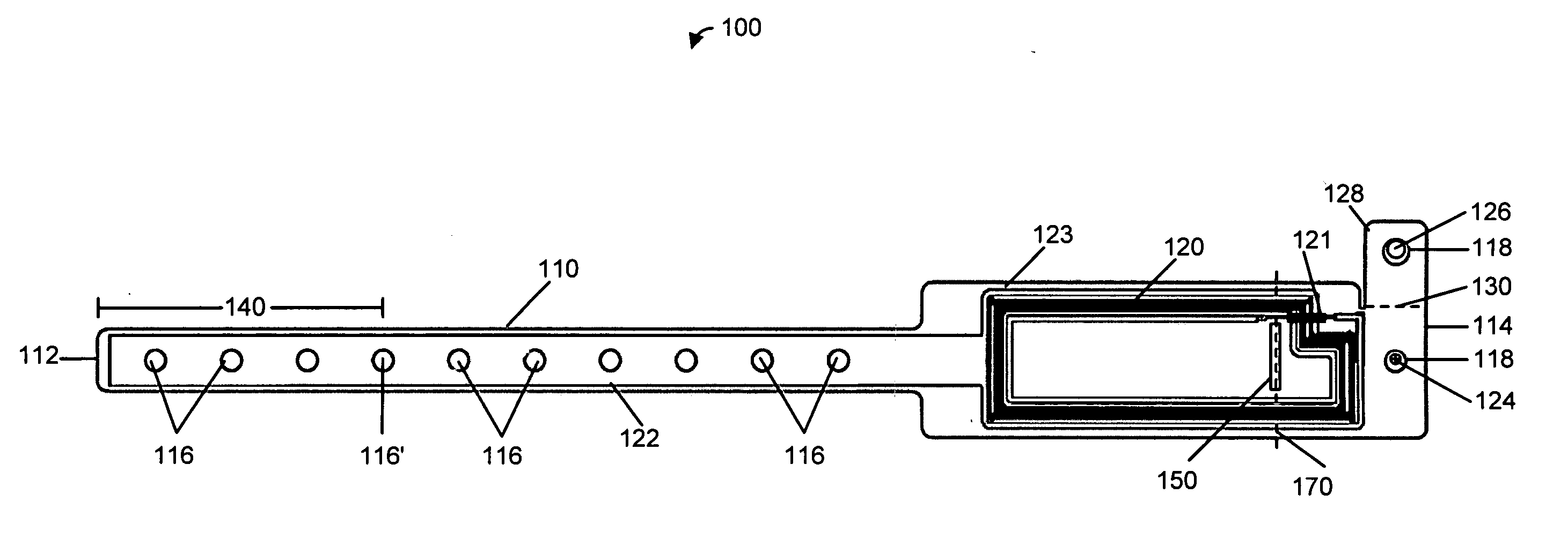
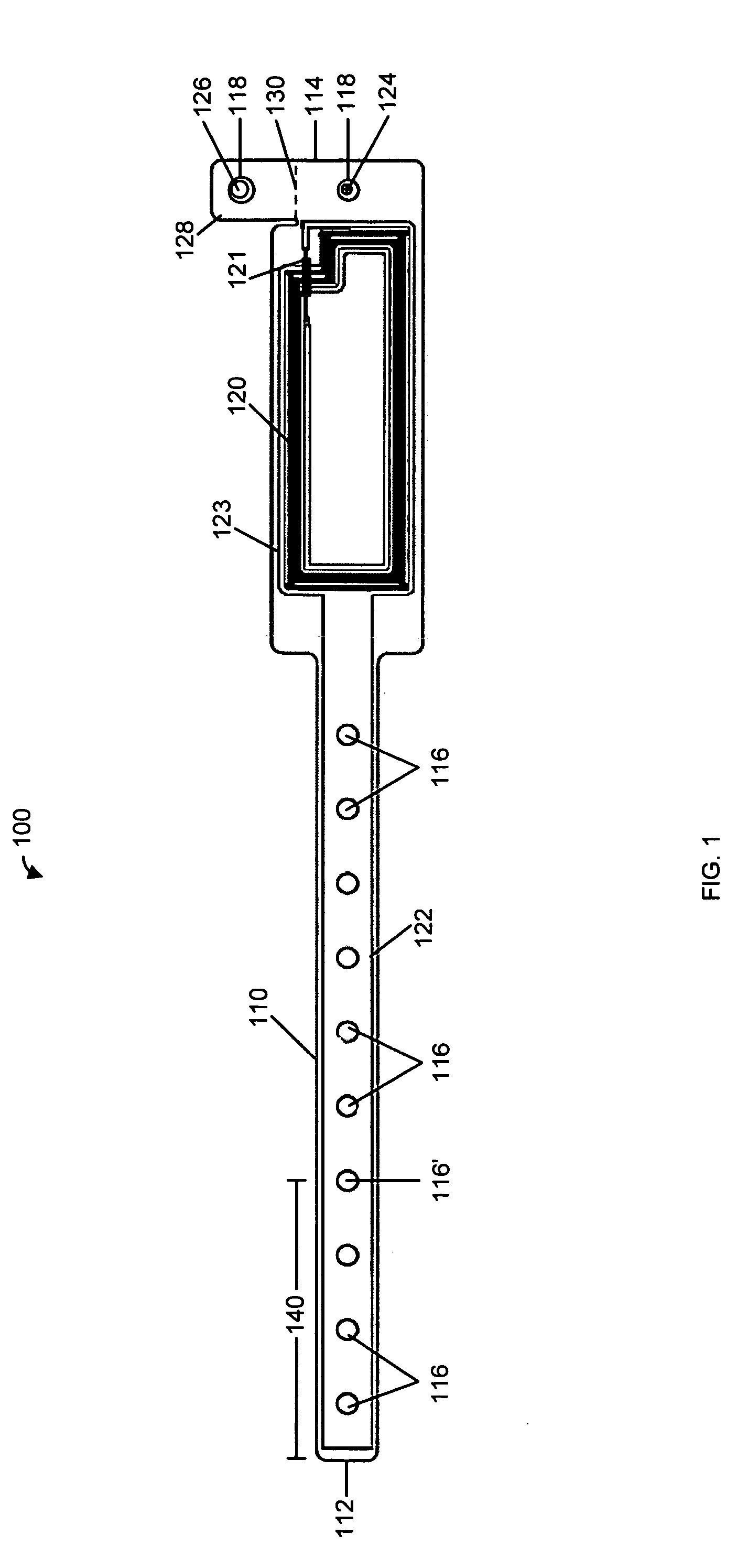
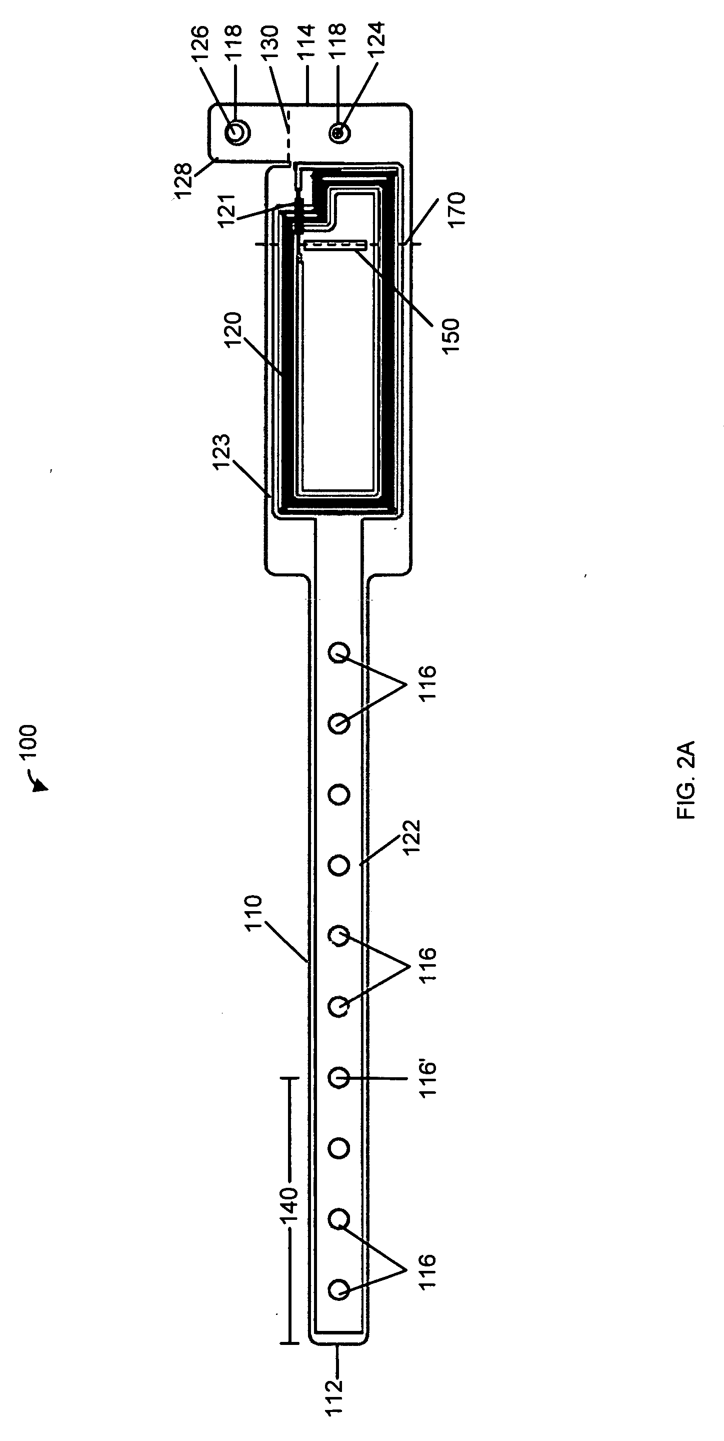
[0018] Generally, passive radio frequency identification (RFID) bracelets include transponder circuits containing an antenna and other additional circuitry that respond to an RF interrogation signal. The additional circuitry is typically provided as a single integrated circuit transponder chip. However, other embodiments are possible, including, for example, an integrated circuit transponder chip incorporated with an external capacitor. In response to the RF interrogation signal, the transponder emits an RF signal representative of information pre-stored or pre-programmed into the transponder. For example, the information could include a serial number, the date the bracelet is issued, the date the bracelet expires and will no longer be usable for access, the age status of the wearer, and / or whether the bracelet can be used for purchasing goods or services. Any other desired information, depending on the context ...


PUM


Abstract

A tamper-resistant RFID identification apparatus that includes a mechanism for storing an excess portion of the apparatus when engaged. The apparatus includes a substrate including a series of holes along a length thereof and a slot distal from the series of holes, a tamper-resistant locking mechanism for securing the apparatus to an object, an RFID circuit disposed on the substrate and an electrically conductive loop disposed on the substrate and electrically coupled to the RFID circuit, that is arranged to disable the RFID circuit when cut. The slot receives a tail portion of the substrate when the apparatus is secured.

Description

BACKGROUND OF THE INVENTION [0001] Bracelets have been used for such things as identification, access control, and age verification for a number of years. For example, various venues may use identification bracelets to quickly and uniquely identify patrons that have access to restricted areas, such as back stage events, alcoholic beverage sales, etc. These bracelets can be made using a narrow band of plastic or other suitable material, so that they are inexpensive to produce and easy to use. However, such bracelets are susceptible to misuse and unauthorized use. Some bracelets are easy to remove, yet still function after removal. A bracelet that still serves its purpose after it has been removed provides the opportunity for patrons to exchange and or sell bracelets. This could provide patrons with the opportunity to give access to a restricted area to an unauthorized patron. For example, a patron with an “adult” bracelet that allows access to alcoholic beverage sales could be remove...

Claims


Application Information

Patent Timeline
Patent Type & Authority Applications(United States)
IPC IPC(8): G08B13/14
CPCG06K19/07381G08B21/0286G09F3/005
Inventor GIRVIN, JOSHUALERCH, JOHN
Owner BARTRONICS HONG KONG
Why Eureka
Try Eureka