Control apparatus and control method of insertion apparatus, insertion apparatus having control apparatus, control program for insertion apparatus, and controlling integrated electronic circuit of insertion apparatus

a technology of control apparatus and control method, which is applied in the direction of program control, instruments, catheters, etc., can solve the problems of dangerous condition, overload, and inability to remove the stuck position,

Active Publication Date: 2014-09-25
PANASONIC INTELLECTUAL PROPERTY MANAGEMENT CO LTD
View PDF2 Cites 59 Cited by
  • Summary
  • Abstract
  • Description
  • Claims
  • Application Information

AI Technical Summary

Benefits of technology

[0022]According to the control apparatus and the control method of the insertion apparatus, the insertion apparatus having the control apparatus, the control program for the insertion apparatus, and the controlling integrated electronic circuit of the insertion apparatus in accordance with the aspects of the present disclosure, a vibration magnitude is adjusted for vibration control depending on a state of the insertion member to carry out vibration control when the insertion member causes getting-stuck in a work for inserting the insertion member. Consequently, it is possible to remove the getting-stuck with a vibration having such a proper magnitude as not to cause an overload. Thus, it is possible to achieve the inserting work.

Problems solved by technology

In some cases in which the vibration magnitude is adapted to either of the states, getting-stuck cannot be removed or an overload occurs.
When the vibration control is applied, therefore, an action for amplifying a jumping state of the flexible member is exerted so that a dangerous condition is brought.

Method used


Image

  • Control apparatus and control method of insertion apparatus, insertion apparatus having control apparatus, control program for insertion apparatus, and controlling integrated electronic circuit of insertion apparatus
  • Control apparatus and control method of insertion apparatus, insertion apparatus having control apparatus, control program for insertion apparatus, and controlling integrated electronic circuit of insertion apparatus
  • Control apparatus and control method of insertion apparatus, insertion apparatus having control apparatus, control program for insertion apparatus, and controlling integrated electronic circuit of insertion apparatus

Examples


first embodiment

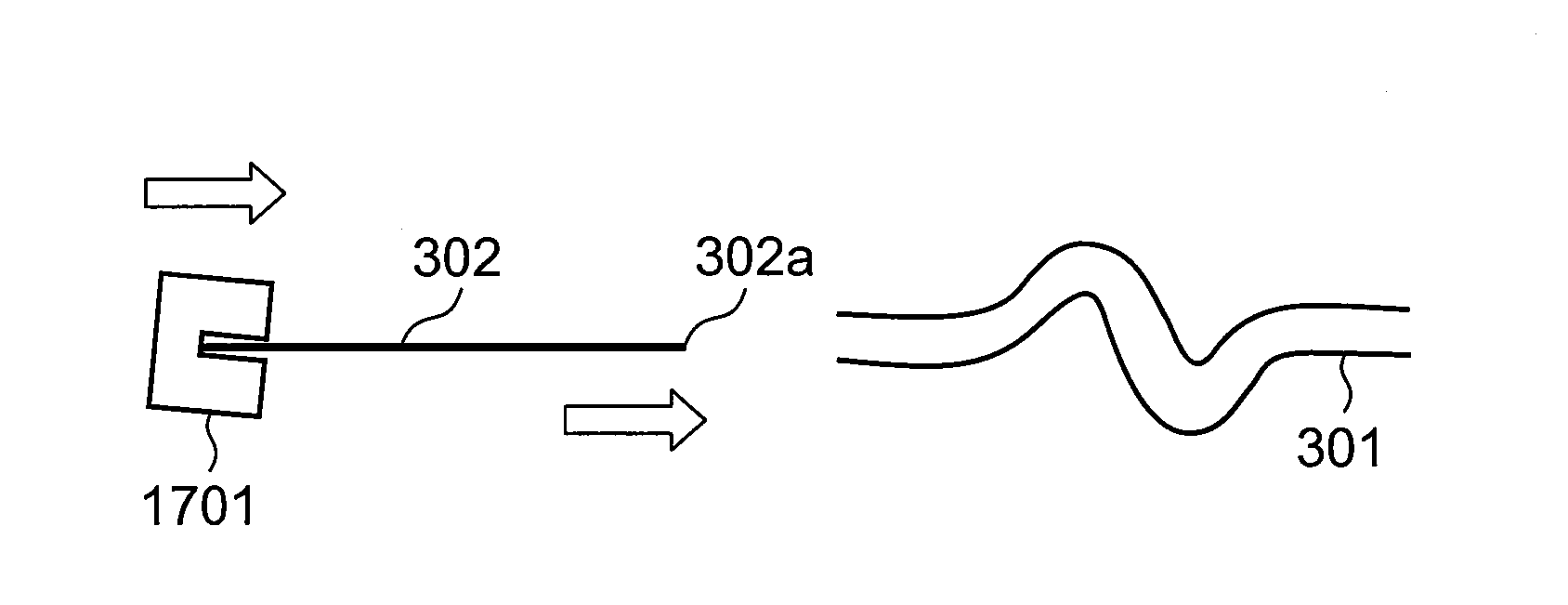
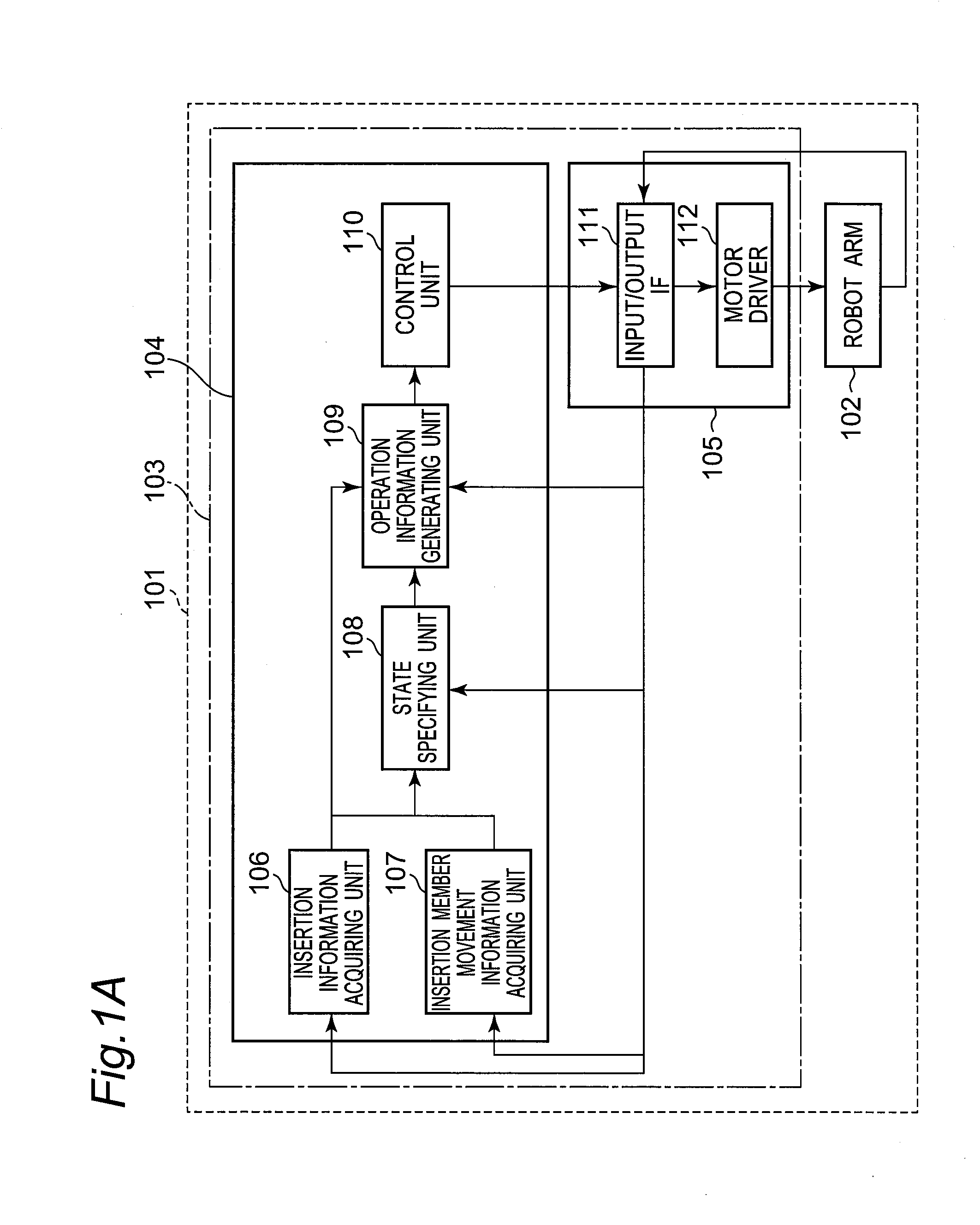
[0227]FIG. 1A is a block diagram showing a robot 101 as an example of an insertion apparatus according to a first embodiment of the present disclosure. In FIG. 1A, the robot 101 is configured from a robot arm 102 and a control apparatus 103 for the robot arm 102 as an example of a control apparatus of the insertion apparatus, and controls an operation so as to insert, into an insertion target of a body lumen 301 such as a blood vessel, an insertion member of a catheter, or an endoscope as an example of an insertion member to be held by a hand 1701 (see FIG. 8A or the like) of the robot arm 102. The insertion apparatus 101 according to the first embodiment of the present disclosure does not need to be a robot but can also be configured by an apparatus such as a roller (details will be described later).

[0228]103 for Robot Arm 102>

[0229]The control apparatus 103 of the robot arm 102 is configured from a control apparatus body unit 104 and a peripheral apparatus 105.

[0230]104>

[0231]The ...

second embodiment

[0379]FIG. 28 is a block diagram showing a robot 101B according to an example of an insertion apparatus in accordance with a second embodiment of the present disclosure. A control apparatus 103B of the robot arm 102 according to an example of a control apparatus of an insertion apparatus in accordance with the second embodiment of the present disclosure has a feature that a control apparatus body unit 104B is provided with a state transition storage unit 2801 and a state specifying unit 2802. Since the robot arm 102; the peripheral apparatus 105; and the insertion information acquiring unit 106, the insertion member movement information acquiring unit 107, the operation information generating unit 109, and the control unit 110 in the control apparatus body unit 104B of the control apparatus 103B in the robot 101B according to the second embodiment of the present disclosure are the same as those in the first embodiment, they have common reference numerals and the description of commo...

third embodiment

[0436]FIG. 38 is a block diagram showing a robot 101C according to an example of an insertion apparatus in accordance with a third embodiment of the present disclosure. A control apparatus 103C of the robot arm 102 according to an example of a control apparatus of an insertion apparatus in accordance with the third embodiment of the present disclosure has a feature that a control apparatus body unit 104C is provided with a state specifying unit 3802 and a control start state specifying unit 3801. Since the robot arm 102; the peripheral apparatus 105; and the insertion information acquiring unit 106, the insertion member movement information acquiring unit 107, the operation information generating unit 109, the control unit 110, and the state transition storage unit 2801 in the control apparatus body unit 1040 of the control apparatus 1030 in the robot 1010 according to the third embodiment of the present disclosure are the same as those in the second embodiment, they have common ref...


PUM


Abstract

A control apparatus of an insertion apparatus in which a state specifying unit specifies a state of an insertion member to carry out vibration control depending on the state, thereby removing getting-stuck of a tip of the insertion member with a vibration having such a proper magnitude as not to cause an overload in a case where the tip of the insertion member is gotten stuck.

Description

CROSS-REFERENCE TO RELATED APPLICATIONS[0001]This is a continuation application of International Application No. PCT / JP2013 / 004147, with an international filing date of Jul. 4, 2013, which claims priority of Japanese Patent Application No.: 2012-154847 filed on Jul. 10, 2012, the content of which is incorporated herein by reference.TECHNICAL FIELD[0002]The technical field relates to a control apparatus and a control method of an insertion apparatus, an insertion apparatus having the control apparatus of an insertion apparatus, a control program for the insertion apparatus, and a controlling integrated electronic circuit of the insertion apparatus, each of which generates an operation of the insertion apparatus for inserting an insertion member of a catheter or an endoscope into a body lumen.BACKGROUND ART[0003]There is proposed an apparatus for detecting movement of a tip part of an endoscope, and detecting getting-stuck of the tip when the amount of the movement of the tip part is ...

Claims


Application Information

Patent Timeline
Patent Type & Authority Applications(United States)
IPC IPC(8): A61B19/00
CPCA61B19/2203A61B2019/2207A61B2019/2211A61B34/30A61B1/0016A61B5/066A61B34/32A61B2017/22001A61B2017/22014A61B2034/301A61M25/01A61M2025/0166G05B19/423G05B2219/37569G05B2219/39195G05B2219/40028G05B2219/45118
Inventor FUDABA, YUDAITSUSAKA, YUKOSATO, TAICHI
Owner PANASONIC INTELLECTUAL PROPERTY MANAGEMENT CO LTD
Why Eureka
Try Eureka