Gold finger and touch screen

a technology of touch screen and gold finger, which is applied in the direction of dielectric characteristics, instruments, printed circuit aspects, etc., can solve the problems of deteriorating the performance of the touch screen, and achieve the effect of ensuring the conductivity of the gold finger, improving the performance of the touch screen, and avoiding falling off or being scratched

Active Publication Date: 2014-10-02
ANHUI JINGZHUO OPTICAL DISPLAY TECH CO LTD
View PDF8 Cites 7 Cited by
  • Summary
  • Abstract
  • Description
  • Claims
  • Application Information

AI Technical Summary

Benefits of technology

[0014]For the above gold finger and touch screen, the gold finger is achieved through adhering an embossable adhesive layer on a side of a substrate, providing grid-shaped grooves on a side of the embossable adhesive layer away from the substrate, embedding a conductive grid in the groove to form a wire. The gold finger is disposed on a sensing component, the wires of the gold finger are electrically connected with the circuit board through an anisotropic conductive adhesive. In this manner, the contact area of the wire and the embossable adhesive layer is increased through embedding the conductive grid of the wire, which is grid-shaped structure, in the grooves such that the wires are tightly combined to the embossable adhesive layer and not easy to fall off or be scratched. Therefore, the conductivity of the gold finger is ensured and the performance of the touch screen is improved.

Problems solved by technology

Since the gold finger made through above two means involves coating silver paste on the surface of the conductive layer, the gold finger tends to fall off or be scratched, thereby deteriorating the conductivity of the gold finger and the performance of the touch screen.

Method used


Image

  • Gold finger and touch screen
  • Gold finger and touch screen
  • Gold finger and touch screen

Examples


Embodiment Construction

[0022]In order to understand the present invention, more comprehensive description of the present invention will be given with reference to the accompany drawings. The drawings give preferred embodiments of the present invention. However, the present invention can be realized through various manners, and is not limited to the embodiments described herein. On the contrary, the aim of providing these embodiments is to make the disclosure of the present invention more clear and comprehensive.

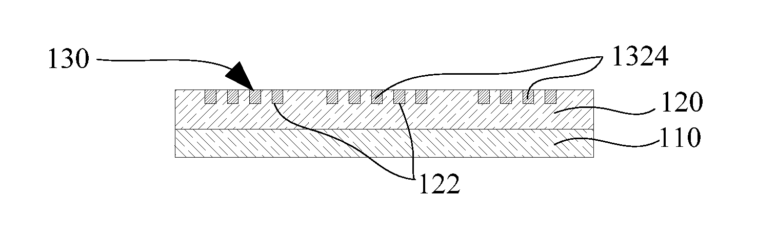
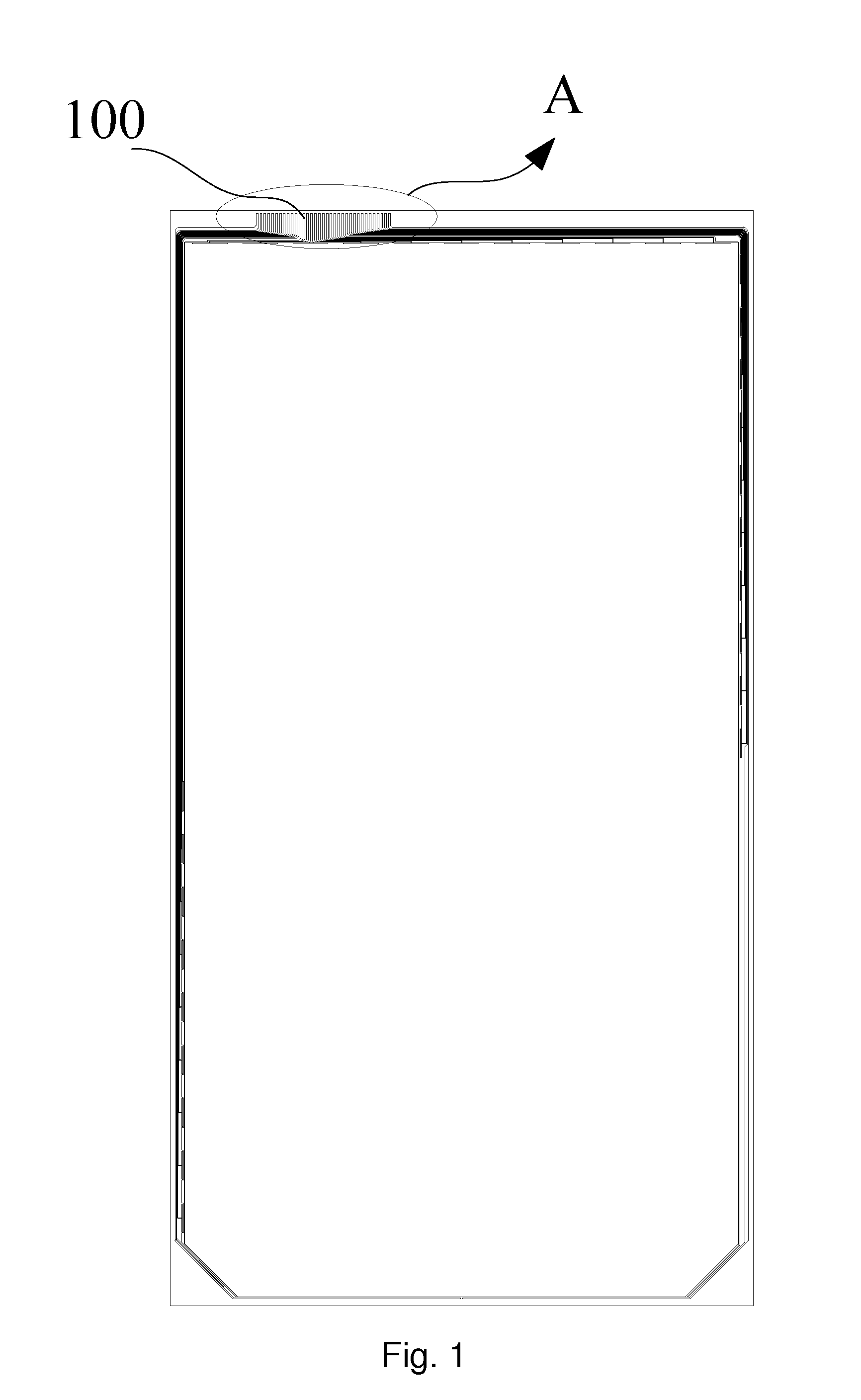
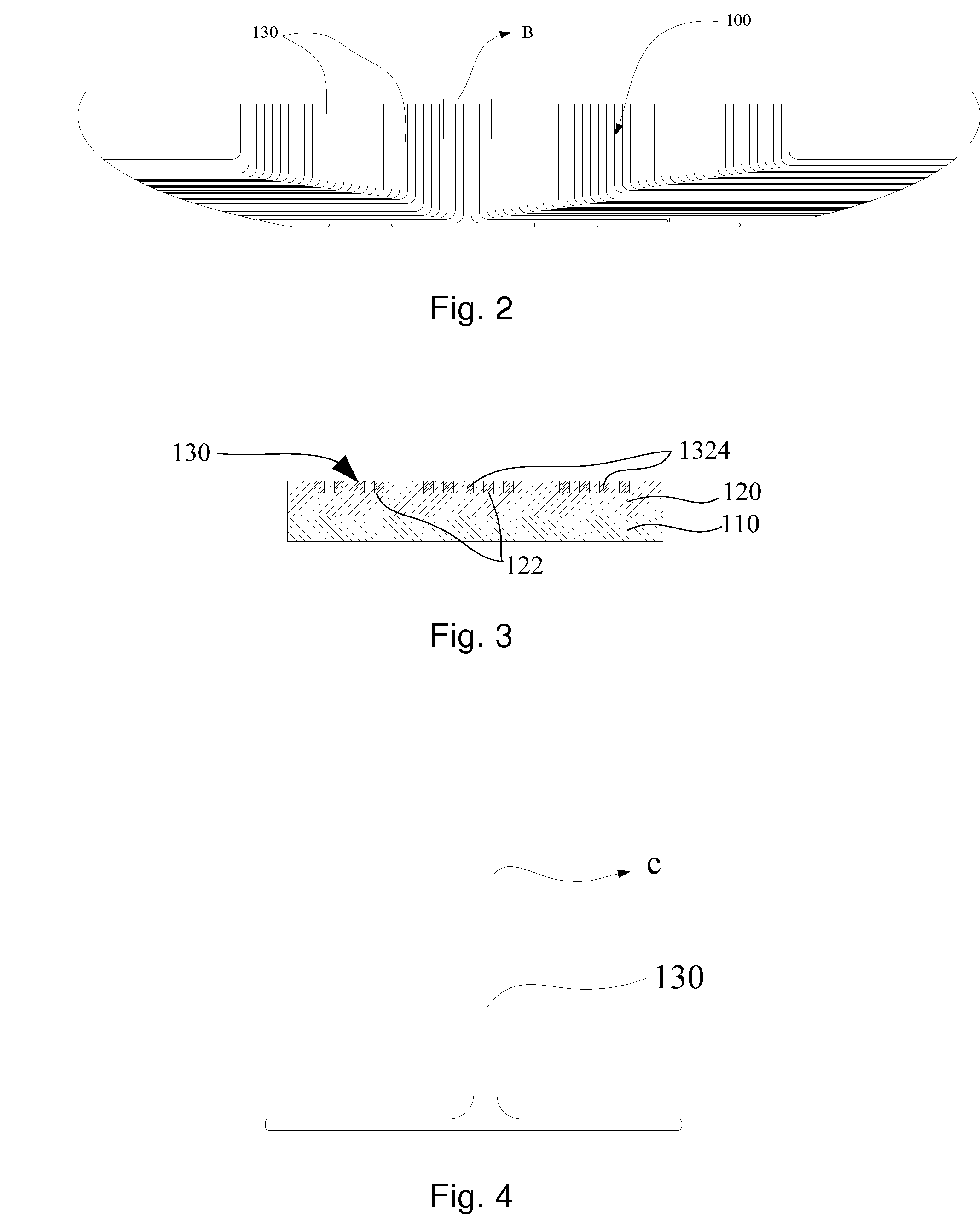
[0023]In an embodiment as shown in FIGS. 1, 2 and 3, a gold finger 100, includes a substrate 110, an embossable adhesive layer 120, and a plurality of wires 130 which can be electrically connected with a circuit board. The embossable adhesive layer 120 is adhered to a side of the substrate 110. A plurality of grid-shaped grooves 122 are defined in a side of the embossable adhesive layer 120 away from the substrate 110. The wires 130 include conductive grids 132 embedded in the grooves 122. For exam...


PUM


Abstract

A gold finger, includes a substrate, an embossable adhesive layer and a plurality of wires. The gold finger is achieved through adhering an embossable adhesive layer to a side of the substrate, providing grid-shaped grooves on a side of the embossable adhesive layer away from the substrate, embedding conductive grids of the wires in the grooves to form the wires. The gold finger is disposed on a sensing component, the wires of the gold finger are electrically connected with a circuit board through an anisotropic conductive adhesive. The contact area of the wire and the embossable adhesive layer is increased through embedding the conductive grid of the wire, which is grid-shaped structure, in the grooves such that the wires are tightly combined to the embossable adhesive layer and not easy to fall off or be scratched. The present invention further provides a touch screen containing the gold finger.

Description

CROSS-REFERENCE TO RELATED APPLICATIONS[0001]This application is a continuation of International Application No. PCT / CN2013 / 079164, filed on Jul. 10, 2013, which claims the priority benefit of China Patent Application No. 201310110313.8, filed on Mar. 30, 2013, both of which are hereby incorporated by reference in their entireties.FIELD OF THE INVENTION[0002]The present invention relates to the field of touch screen technology, in particular to a gold finger and a touch screen.BACKGROUND OF THE INVENTION[0003]A touch screen is an inductive device able to receive an input signal such as a touch etc. The touch screen is a brand new information interaction device that gives information interaction a new look. The development of touch screen technique has attracted extensive attention in information media at home and abroad. A conductive layer of the touch screen is electrically connected with a Flexible Printed Circuit Board (FPCB) through an electrode lead. A part of the electrode lea...

Claims


Application Information

Patent Timeline
Patent Type & Authority Applications(United States)
IPC IPC(8): H05K1/09
CPCH05K1/09H05K1/117G06F3/041H05K3/1258H05K2201/0108H05K2201/026H05K2201/0376
Inventor TANG, GENCHUDONG, SHENGCAILIU, WEITANG, BIN
Owner ANHUI JINGZHUO OPTICAL DISPLAY TECH CO LTD
Why Eureka
Try Eureka