
Borehole Log Data Processing Methods

a technology of boreholes and log data, applied in the field of improved borehole log data processing methods, can solve the problems of ghosting, inability to accurately predict the effect of the color of the same well, and inability to achieve the effect of improving the detail

Active Publication Date: 2014-10-02
REEVES WIRELINE TECH
View PDF4 Cites 4 Cited by
  • Summary
  • Abstract
  • Description
  • Claims
  • Application Information

AI Technical Summary

Benefits of technology

The patent describes a method to improve the quality of image logs used in oil and gas drilling. The method separates out the illumination data and reflectance data in the log data, allowing for selective filtering to reduce the effects of the illumination data. This results in a log that has a wider dynamic range, making it possible to render more information using a fixed color scale. The method can be applied to all the data contributing to the image log, but it is especially useful for fine or difficult-to-resolve features. The combination of static and dynamic normalization characteristics in the image log is likely to be beneficial in the interpretation of the logs.

Problems solved by technology

In part the difficulties derive from techniques of normalization (i.e. the assignment of the log data values to the range of colours available for inclusion in an image log) that are currently in use.
The disadvantage is that the resistivity of rocks spans several orders of magnitude, so small but significant variations in resistivity within a narrow band are not rendered with this method.
The disadvantage is that the same color from different parts of the same well will not in general correspond to the same resistivity value.
This means that the color mapping applied to the depth frame at the central depth in the window is influenced by resistivity values elsewhere in the window, and this has the potential to create ghosts when the window contains high-contrast transitions.
Ghosting therefore leads to significant inaccuracies, and the loss of some features from the image logs altogether.

Method used


Image

  • Borehole Log Data Processing Methods
  • Borehole Log Data Processing Methods
  • Borehole Log Data Processing Methods

Examples


Embodiment Construction

[0093]Referring to the representations, the methods of the invention are described in the following sections, in which the sub-headings indicate the various aspects of the invention.

[0094]Illumination-Reflectance Model

[0095]An image can be considered as a 2D function of the form i(x, y), value of which at spatial coordinates (x,y) is a positive scalar quantity physical meaning of which is determined by the source of the image. In the case of grayscale images, when an image is generated from a physical process its values are proportional to energy radiated by a physical source. In other words, an image is an array of measured light intensities that are a function of the amount of light reflected off the objects in the scene.

[0096]The intensity is a product of illumination (the amount of source illumination incident on the scene being viewed) and reflectance (the amount of illumination reflected by the objects in the scene). Note that this is still valid for resistivity log images, ev...


PUM


Abstract

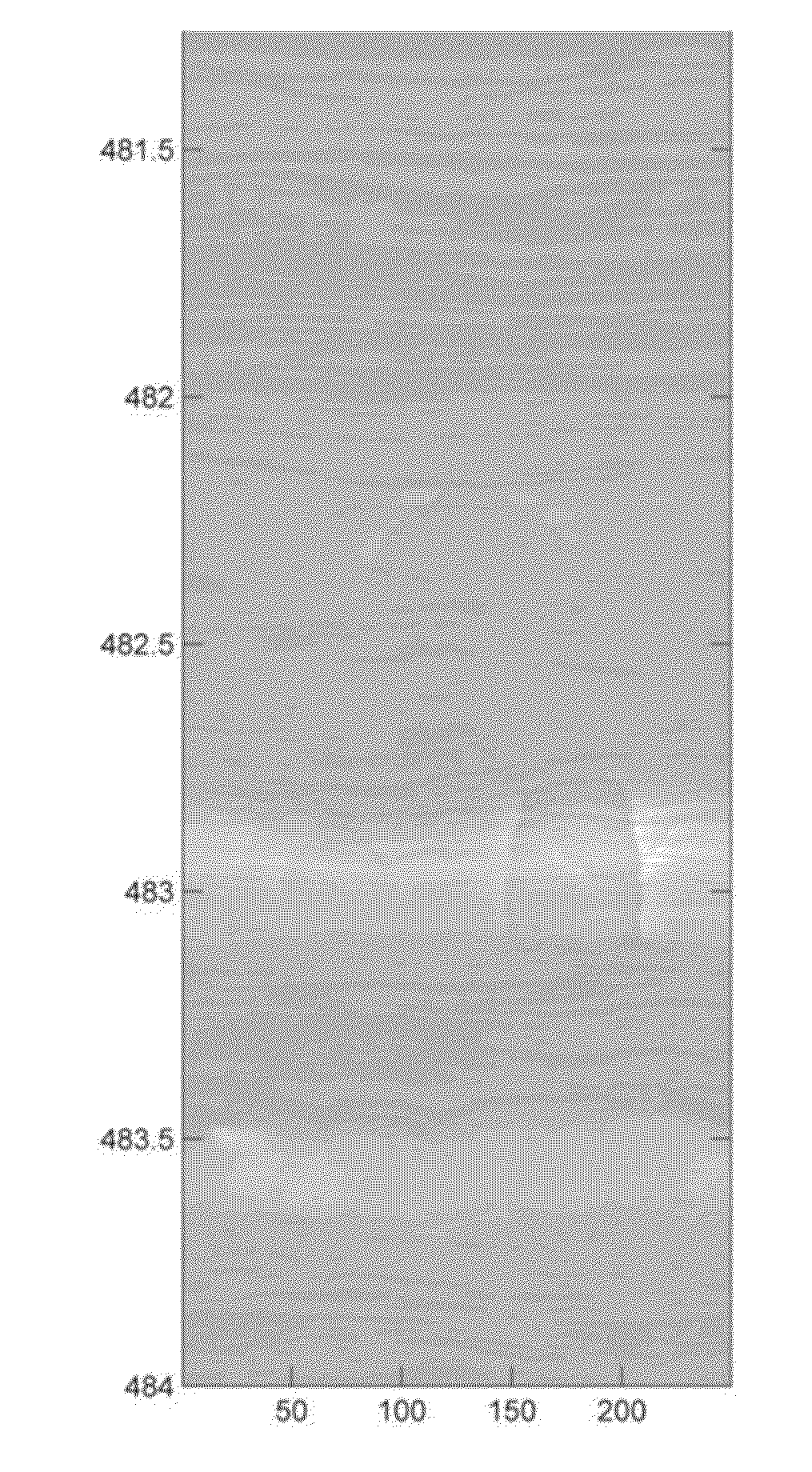
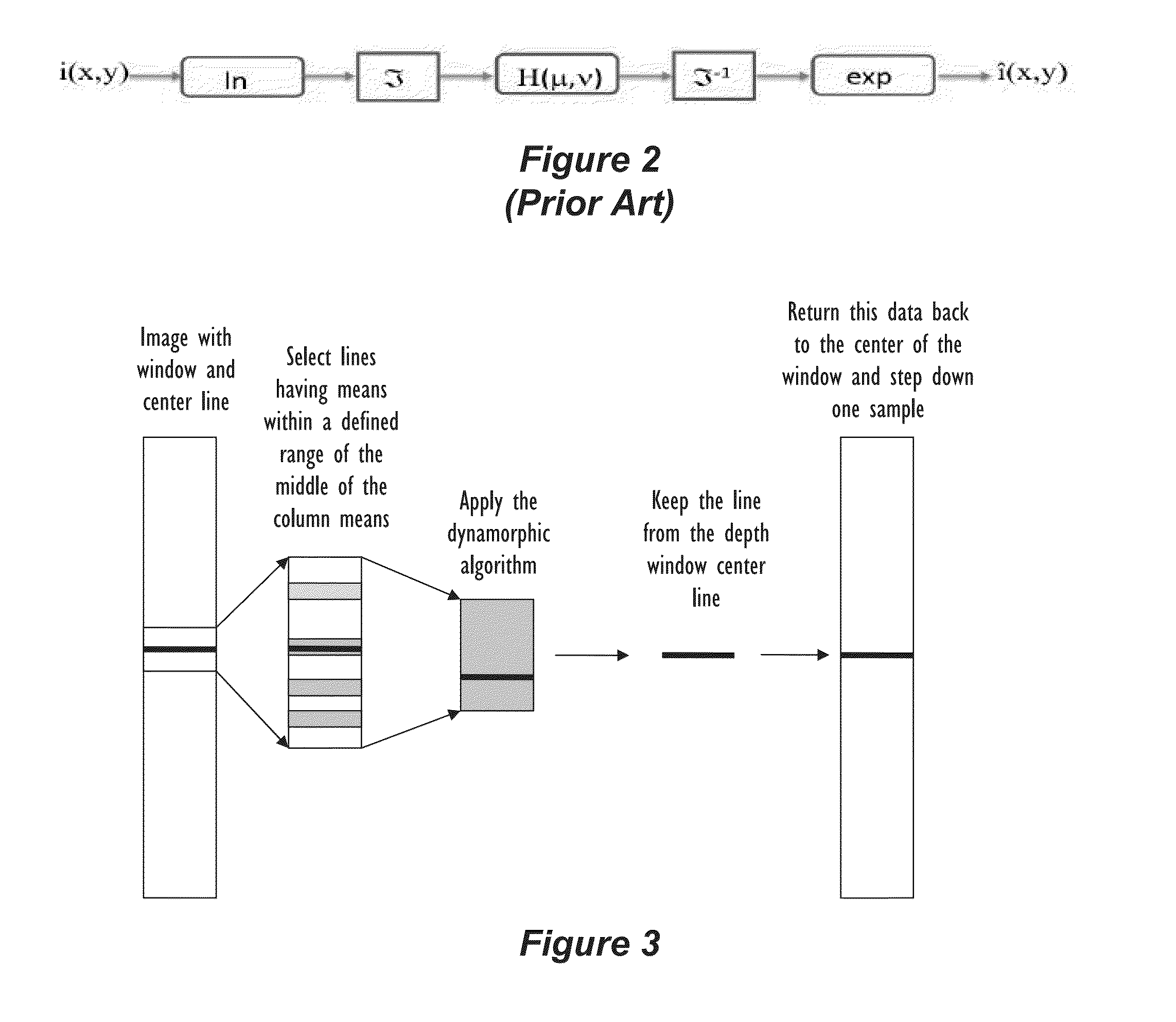
A method of processing borehole log data to create one or more image logs involve modeling the log data as components of an image in the form i(x, y)=l(x, y)×r(x, y) (1), in which i(x, y) is an image representative of the log data, l(x, y) denotes an illumination value of the image at two-dimensional spatial co-ordinates x, y, and r(x, y) denotes a surface reflectance value at the co-ordinates x, y. Equation (1) is transformed to a logarithmic domain, and a Fourier transform is obtained of the resulting logarithmic domain expression to obtain a Fourier domain expression. The Fourier domain expression is high-pass filtered, and an inverse Fourier transform is obtained of the resulting filtered Fourier domain expression. An exponential operation is performed on the result of inverse Fourier transform to obtain a filtered image model expression. Values of the filtered image model expression are mapped to respective color values across the range of the filtered image model expression values. The mapped color values can then be displayed, printed, saved and / or transmitted as one or more image logs.

Description

FIELD OF THE DISCLOSURE[0001]The invention relates to improved borehole log data processing methods.BACKGROUND OF THE DISCLOSURE[0002]The logging of geological formations is, as is well known, economically a highly important activity. The invention is of benefit in logging activities potentially in all kinds of mining and especially in the logging of reserves of oil and gas, water or other valuable commodities.[0003]Virtually all commodities used by mankind are either farmed on the one hand or are mined or otherwise extracted from the ground on the other, with the extraction of materials from the ground providing by far the greater proportion of the goods used by humans.[0004]It is extremely important for an entity wishing to extract materials from beneath the ground to have as good an understanding as possible of the lithology of a region from which extraction is to take place.[0005]This is desirable partly so that an assessment can be made of the quantity and quality, and hence th...

Claims


Application Information

Patent Timeline
Patent Type & Authority Applications(United States)
IPC IPC(8): G06T11/20
CPCG06T11/206G01V3/24G01V3/38G06T11/00E21B47/01E21B47/113G01V11/00G06T5/77G06T15/80G03B37/005G06T11/003E21B49/00
Inventor ELKINGTON, PETER ADRIAN SPENCERASSOUS, SAIDWHETTON, JAMES
Owner REEVES WIRELINE TECH
Learn More