Eureka AIR delivers breakthrough ideas for toughest innovation challenges, trusted by R&D personnel around the world.

PTC Device

a technology of ptc device and ptc device, which is applied in the direction of emergency protective circuit arrangement, electrical apparatus, and arrangements responsive to excess current, can solve problems such as abnormal temperature rise, and achieve the effect of improving the productivity of ptc device and efficient production of ptc devi

Inactive Publication Date: 2014-10-02
LITTELFUSE JAPAN GK
View PDF5 Cites 0 Cited by
  • Summary
  • Abstract
  • Description
  • Claims
  • Application Information

AI Technical Summary

Benefits of technology

The present invention provides a PTC device that uses a lead with a concave portion, which prevents the formation of protruding solder paste during production. This improves the efficiency and productivity of the PTC device. Additionally, the invention prevents excess epoxy resin from adhering to the jig, which reduces the likelihood of the oxygen barrier layer being compromised.

Problems solved by technology

Also, the PTC device is widely used as a protection device which interrupts a current flow through the apparatus when such electric element fails so that its temperature rises abnormally.

Method used


Image

  • PTC Device
  • PTC Device
  • PTC Device

Examples


Embodiment Construction

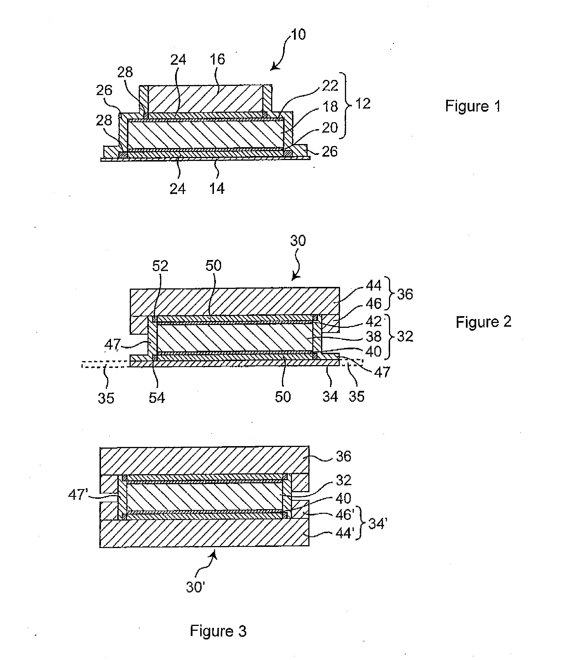
[0031]Next, the PTC device according to the present invention will be explained in detail with reference to the accompanied drawings. A configuration of one embodiment of the PTC device according to the present invention is schematically shown in its cross-sectional view in FIG. 2 wherein one of the two leads has a concave portion. The illustrated PTC device can be used, for example, as a circuit protection device for a secondary cell.

[0032]The PTC device 30 comprises a PTC member 32 and leads 34 and 36 which are electrically connected to the both sides of the PTC member respectively. In the illustrated embodiment, one lead 34 is, for example, a substrate side lead which is connected to a circuit board, and the other lead 36 is, for example, a cell side lead which is connected to a secondary cell. Similarly to the embodiment shown in FIG. 1, the PTC member 32 comprises a PTC element 38 in the form of a layer which is made of an electrically conductive PTC composition as well as meta...


PUM


Abstract

The present invention relates to a new PTC device having a configuration with which protrusion of solder paste and / or an excess portion of epoxy resin do not adversely affect a jig. Such PTC device 30 includes a PTC member 32 and leads 34 and 36 electrically connected to both sides of the PTC member. The PTC member includes a PTC element 38 and metal electrodes 40 and 42 placed on both sides of the PTC element respectively, and each lead is electrically connected to the metal electrode via an electrically conductive connection portion 50. At least one of the leads 36 has a concave portion which is defined with a bottom portion 44 located adjacently to the metal electrode of the PTC member and a wall portion 46 surrounding the electrically conductive connection portion which connects the leads to the metal electrode.

Description

TECHNICAL FIELD[0001]The present invention relates to a PTC device which comprises a PTC (Positive Temperature Coefficient) member and leads which are connected to the both sides of the PTC member. In particular, the present invention relates to a PTC device which comprises a PTC member having a laminar polymer PTC element and metal electrodes placed on the both sides of the PTC element as well as leads which are electrically connected to the metal electrodes respectively.BACKGROUND ART[0002]The above described PTC device is widely used as a protection device which protects an electric element (such as a secondary cell) constructing various electric apparatuses or a circuit constructing such electric apparatuses when an excessive amount of current passes through the apparatuses. Also, the PTC device is widely used as a protection device which interrupts a current flow through the apparatus when such electric element fails so that its temperature rises abnormally.[0003]One example of...

Claims


Application Information

Patent Timeline
Patent Type & Authority Applications(United States)
IPC IPC(8): H02H3/08
CPCH02H3/085
Inventor KOYAMA, HIROYUKI
Owner LITTELFUSE JAPAN GK
Why Eureka
Eureka Blog
Learn More