Method of generating path of multiaxial robot and control apparatus for the multiaxial robot

a multi-axial robot and control apparatus technology, applied in the direction of electric programme control, program control, instruments, etc., can solve the problems of insufficient acceleration/deceleration at other action points than the action points mentioned, the maximum acceleration change is non-linear, and the acceleration/deceleration cannot be minimized, so as to prevent the movement velocity of the robot from being enhanced, increase the acceleration required, and increase the deceleration required

Active Publication Date: 2014-10-02
DENSO WAVE INC
View PDF4 Cites 24 Cited by
  • Summary
  • Abstract
  • Description
  • Claims
  • Application Information

AI Technical Summary

Benefits of technology

[0017]In the control of a conventional multiaxial robot, an axis whose amount of movement does not change between the start and end points will stay still in a simple work which is based such as on a pick-and-place pattern. When such an axis stays still, an end effector-side arm (second link) only imposes a load on a base-side arm (first link). The load on the base-side arm is so large that the load will prevent the movement velocity of the robot from being enhanced.
[0018]On the other hand, when a path is generated as described above, the end effector-side arm moves, on an end side of the base-side arm, such that a reaction is caused in the base-side arm. Accordingly, the path generated as described above can increase the acceleration required in starting the end effector and increase the deceleration required in stopping the end effector. Accordingly, the velocity of moving the end effector from the start point to the end point is increased to decrease the time duration of the robot. In this case, the following relations are established:
[0019]However, most of the robots spread recently have a high reduction gear ratio. Accordingly, the maximum joint velocity of such a robot is low based on the Relation (B), and thus the above operation allows the joint velocity to reach its upper velocity limit in a shorter time. Therefore, the only way of shortening the time duration is to achieve a steep

Problems solved by technology

However, since the actual posture of the multiaxial robot changes moment by moment, the maximum acceleration changes in a non-linear manner.
Therefore, the motors are not able to sufficiently exert their performances.
However, it is unclear in this patent document how the preset limiting acceleration curve is calculated.
Accordingly, in this control method: (1) a plurality of parameters are provided and thus the m

Method used


Image

  • Method of generating path of multiaxial robot and control apparatus for the multiaxial robot
  • Method of generating path of multiaxial robot and control apparatus for the multiaxial robot
  • Method of generating path of multiaxial robot and control apparatus for the multiaxial robot

Examples


first embodiment

[0042]Referring to FIGS. 1 to 11, hereinafter are described a method of generating a path (or trajectory) of a multiaxial robot and a control apparatus for the multiaxial robot, according to a first embodiment of the present invention.

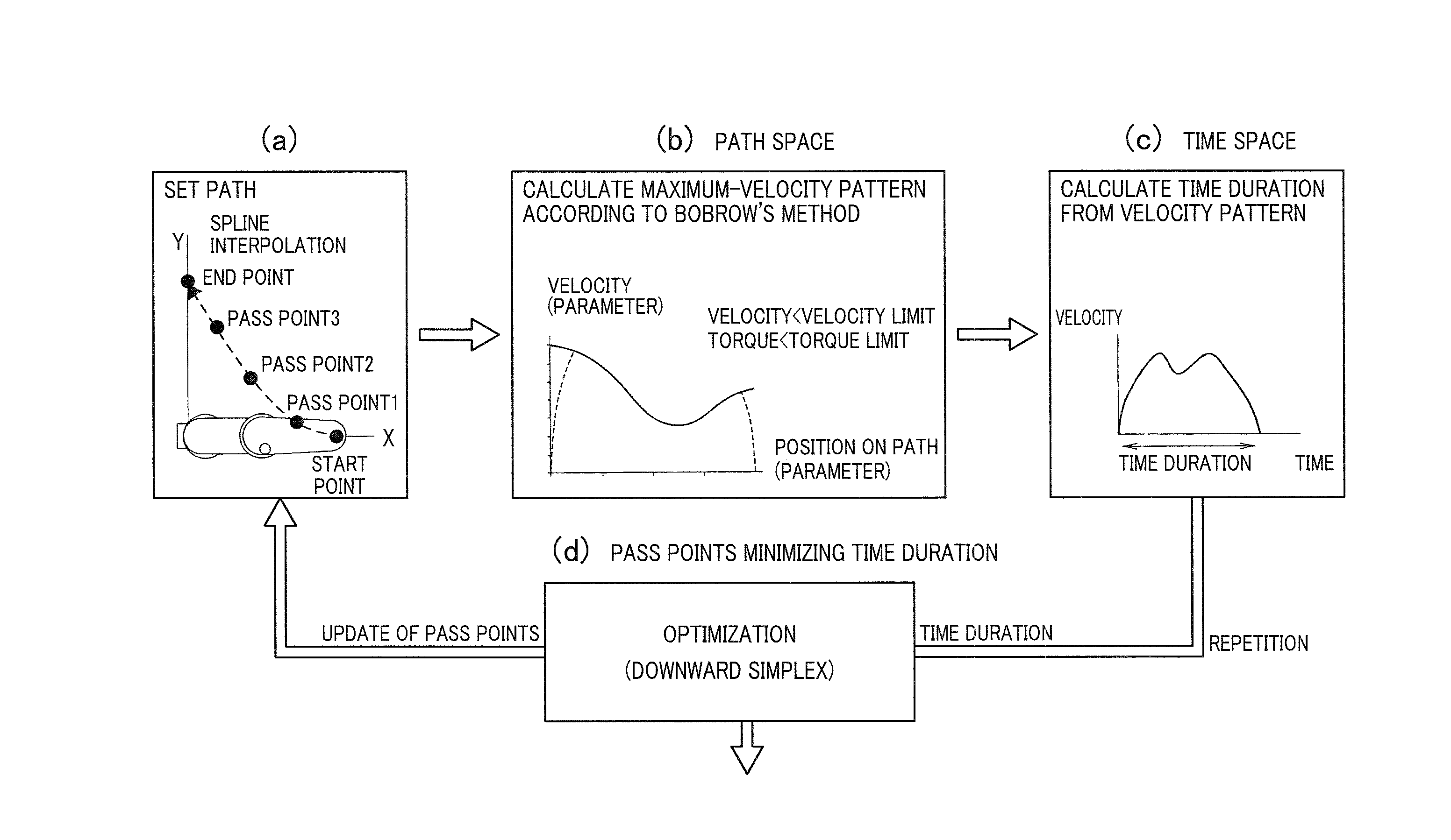
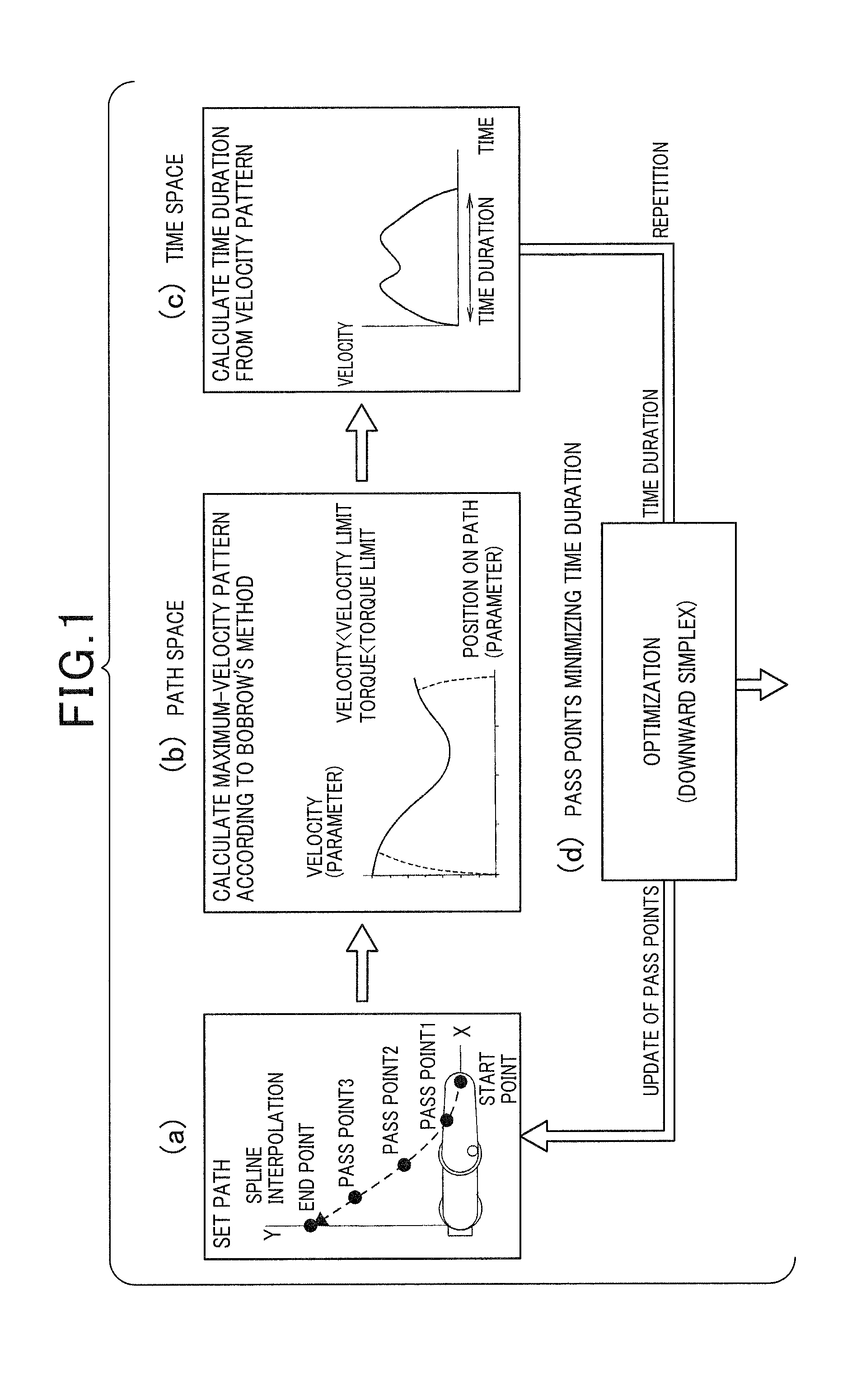
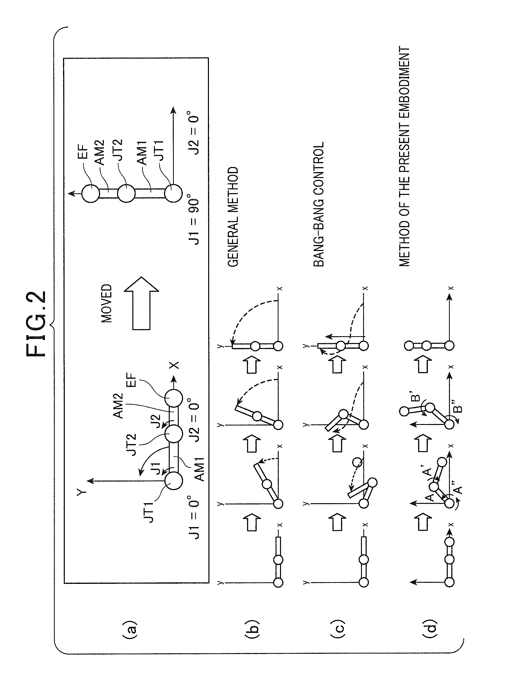
[0043]Before specifically describing an example of the multiaxial robot, referring to FIGS. 1 and 2, an outline of a control method of the multiaxial robot of the present embodiment is described. First, referring to (a) to (d) of FIG. 2, the control method of the present embodiment is described comparing with a control method based on conventional art.

[0044]As shown in FIG. 2(a), let us assume a simple biaxial robot (having axes J1 and J2) in which first and second arms (links) AM1 and AM2 are combined into one arm so as to be movable about two joints JT1 and JT2, respectively. An end effector EF of the robot is moved on the X-Y plane from an angular position (J1, J2)=(0°, 0°) to an angular position (J1, J2)=(90°, 0°).

[0045]As shown in FIG. 2(b), the s...

second embodiment

[0115]Referring to FIGS. 12 and 13, hereinafter is described a second embodiment related to a method of generating a path of a multiaxial robot and a control apparatus for the multiaxial robot.

[0116]In the second and the subsequent embodiments, the components identical with or similar to those in the control apparatus of the first embodiment are given the same reference numerals for the sake of omitting or simplifying explanation.

[0117]In the method of generating a path of a multiaxial robot and a control apparatus for the multiaxial robot according to the second embodiment, there is a change in the timing of performing the step of converting the position x of an end effector to the angle q of each axis. Specifically, in the first embodiment described above, the position x of the end effector is converted to the angle q of each axis by solving the inverse kinematics (refer to step S12). In this regard, in the second embodiment, conversion to the angle q is performed at a stage prior...


PUM


Abstract

In a multiaxial robot, a path along which the end effector of the robot moves in the shortest time duration is generated. The robot includes a first link and a second link positioned closer to an end effector than the first link. Start and end points are specified, and velocity patterns are generated for joints driving the first and second links based on the specified start end points. The velocity patterns enable a movement of the second link to cause i) a reaction for increasing an acceleration force generated by the first joint when the end effector is started to be moved from the start point toward the end point, and ii) a reaction for increasing a deceleration force generated by the first joint when the end effector is stopping to the end point.

Description

BACKGROUND OF THE INVENTION[0001]1. Technical Field of the Invention[0002]The present invention relates to a method of generating a path to accelerate the movement velocity of a multiaxial robot and relates to a control apparatus for the multiaxial robot.[0003]2. Related Art[0004]Recently, in the field site such as of a productive facility, great variety of industrial robots is used. Such industrial robots include so-called multiaxial robots having a plurality of joints (axes). Such multiaxial robots are used for the works of welding, coating, parts assembly, parts conveyance, and the like. Such a multiaxial robot, by the nature of the role played by it, is required to reduce its time duration from a start point to an end point, i.e. required to increase movement velocity.[0005]Methods of controlling the acceleration / deceleration of the movement of a multiaxial robot for increasing movement velocity are well known. For example, according to one of such methods, a basic movement velo...

Claims


Application Information

Patent Timeline
IPC IPC(8): B25J9/16
CPCB25J9/1651B25J9/1664G05B2219/40519G05B2219/43062G05B2219/43093G05B2219/43203G05B2219/39407G05B19/416G05B2219/40527
Inventor IWASAKI, YOSHIROU
Owner DENSO WAVE INC
Why Eureka
Try Eureka