Laser machining apparatus

a technology of laser machining and machining equipment, which is applied in the direction of laser beam welding equipment, manufacturing tools, instruments, etc., can solve the problem of inability to accurately measure the height position of the upper face of the wafer, and achieve the effect of wide measurement range, accurate measurement of the height position of the workpiece, and high detection speed

Active Publication Date: 2014-10-09
DISCO CORP
View PDF4 Cites 20 Cited by
  • Summary
  • Abstract
  • Description
  • Claims
  • Application Information

AI Technical Summary

Benefits of technology

[0008]The above interferometric height position detector features a wide measurement range and high detection speed. In contrast, the confocal optical height position detector is advantageous in that it can accurately measure the height position of a workpiece although lower in detection speed than the interferometric height position detector.

Problems solved by technology

However, in the case of an optical device wafer having a light-emitting layer formed on the front face of a sapphire substrate and a reflecting film called DBR (Distributed Bragg Reflector) film adapted to provide improved brightness formed on the rear face of the sapphire substrate, the interference may be disturbed between light reflected from the upper face position of the wafer held by a chuck table to which a laser beam is to be irradiated and reference light, possibly making it impossible to properly measure the position of the upper face of the wafer.

Method used


Image

  • Laser machining apparatus
  • Laser machining apparatus
  • Laser machining apparatus

Examples


Embodiment Construction

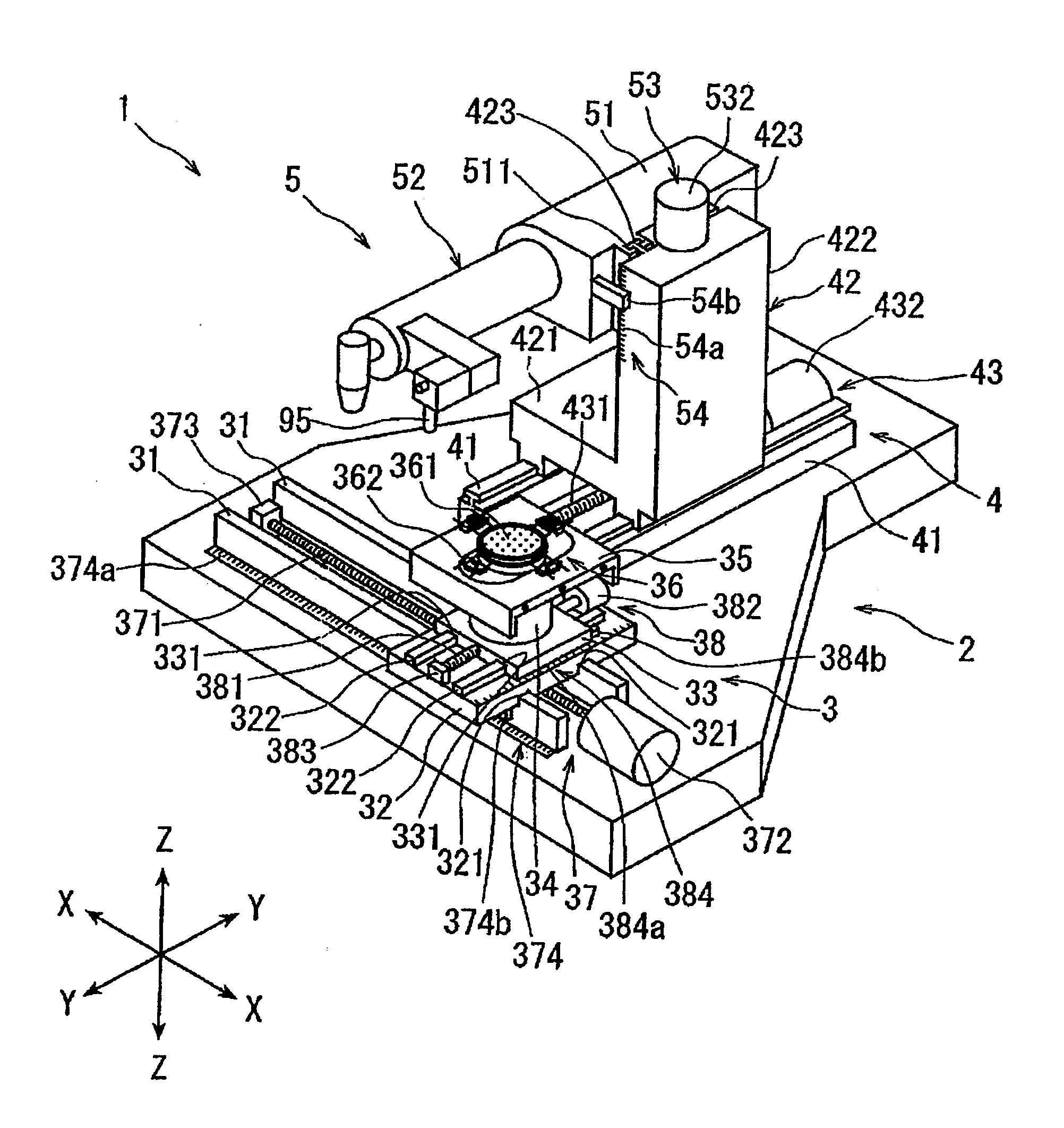
[0028]A detailed description will be given below of a preferred embodiment of the present invention with reference to the accompanying drawings. FIG. 1 illustrates a perspective view of a laser machining apparatus configured in accordance with the present invention. A laser machining apparatus 1 illustrated in FIG. 1 includes a stationary base 2, a chuck table mechanism 3, a laser beam irradiation unit support mechanism 4, and a position detection / laser irradiation unit 5. The chuck table mechanism 3 is arranged on the stationary base 2 in a manner movable in a machining feed direction shown by an arrow X (X-axis direction) to hold a workpiece. The laser beam irradiation unit support mechanism 4 is arranged on the stationary base 2 in a manner movable in an indexing feed direction shown by an arrow Y (Y-axis direction). The indexing feed direction is orthogonal to the X-axis direction. The position detection / laser irradiation unit 5 is arranged on the laser beam irradiation unit sup...


PUM

PropertyMeasurementUnit
wavelength rangeaaaaaaaaaa
wavelengthaaaaaaaaaa

Abstract

A laser machining apparatus that includes an interferometric height position detection unit, a condensing point position adjustment unit, and a confocal optical height position detection unit. A controller of the laser machining apparatus specifies, as a correction value, the difference between the two height positions of the upper face of the workpiece, one detected by the confocal optical height position detection unit and the other detected by the interferometric height position detection unit. The controller controls the condensing point position adjustment unit based on the height position obtained by correcting the height position of the upper face of the workpiece detected by the interferometric height position detection unit using the correction value.

Description

BACKGROUND OF THE INVENTION[0001]1. Field of the Invention[0002]The present invention relates to a laser machining apparatus having functionality to detect the height position of the upper face of a workpiece held by a chuck table adapted to hold a workpiece.[0003]2. Description of the Related Art[0004]In a semiconductor device manufacturing process, devices such as ICs or LSIs are formed in a plurality of partitioned areas on the front face of an approximately disc-shaped semiconductor wafer. The plurality of areas are partitioned by a plurality of scheduled division lines called streets. The streets are arranged in a grid pattern. Then, the semiconductor wafer is cut along the streets, thus dividing the areas having devices formed therein and manufacturing individual semiconductor devices. On the other hand, an optical device wafer is formed by stacking a light-emitting layer made up of p- and n-type semiconductor layers, for example, on the front face of an approximately disc-sha...

Claims


Application Information

Patent Timeline
Patent Type & Authority Applications(United States)
IPC IPC(8): B23K26/04
CPCB23K26/046B23K26/032B23K26/04B23K26/042B23K26/359G01B11/00H01L21/68
Inventor SAWABE, TAIKIONOE, WAKANAENDO, TOMOHIRO
Owner DISCO CORP
Why Eureka
Try Eureka