Outside the workplace the widespread use of personal listening devices has led to widespread concerns about potential hearing damage with prolonged use.
Acoustic levels delivered by the earpieces can also be limited in various ways, with source-limiting, or various limiting techniques at the earpieces.
However, clear communications can be compromised if earpiece generated acoustic levels are limited to the extent that residual ambient
noise is too high, either generally or for short periods.
These do not always deliver as high an audio level as is safe for short periods, and so communications intelligibility can suffer significantly.
Other more sophisticated options are more expensive, use more power and are relatively large in size compared with what is convenient in many applications.
Both these factors limit the availability of effective solutions to prevent potentially damaging levels of sound exposure.
In setting a limit for the earpiece dose based on such assessments, the limited level may be insufficient for clear communications, which in some situations can lead to compromised safety.
Such solutions fail to make use of the full range of safe dose levels as defined by the legislation.
Mistakes in any of these can result in hearing damage.
However, a test tone at a certain
peak level has many times more potential to damage hearing than occasional spoken words at the same
peak level.
This leads to loss of communication
clarity in some adverse ambient
noise environments.
These limit the peak
voltage getting to the earpiece, but suffer from all of the problems associated with the above as well as significant
distortion of peak signals and inadequacy in terms of limiting
acoustic energy in the ear to safe levels.
They do not base the controlled level on the output and are consequently not accurate.
The
operating limit still has to be based on an assessment of programme content as it is not able to monitor actual dose or respond specifically to accumulated dose.
Some variants are not able to work at some of the lower
signal levels used in IEMs, but others incorporate transformers which allow the necessary high control voltages to be generated.
However, they do not deal with hearing dose exposure.
Because of the computation necessary to determine dose, these are generally based on sophisticated
processing in
digital signal processors (DSPs) and hence are relatively expensive in comparison with the cost of many hearing devices, need more power than is easily available in most circumstances, and are bulky.
Hence they are not optimum solutions for the majority of earpiece users.
However this necessitates additional power to drive the hearing device.
However this offers no inherent protection for dose or for peak
signal levels.
Hence there is likely to be an undesirable effect on
frequency response and audio quality, especially with high levels of attenuation.
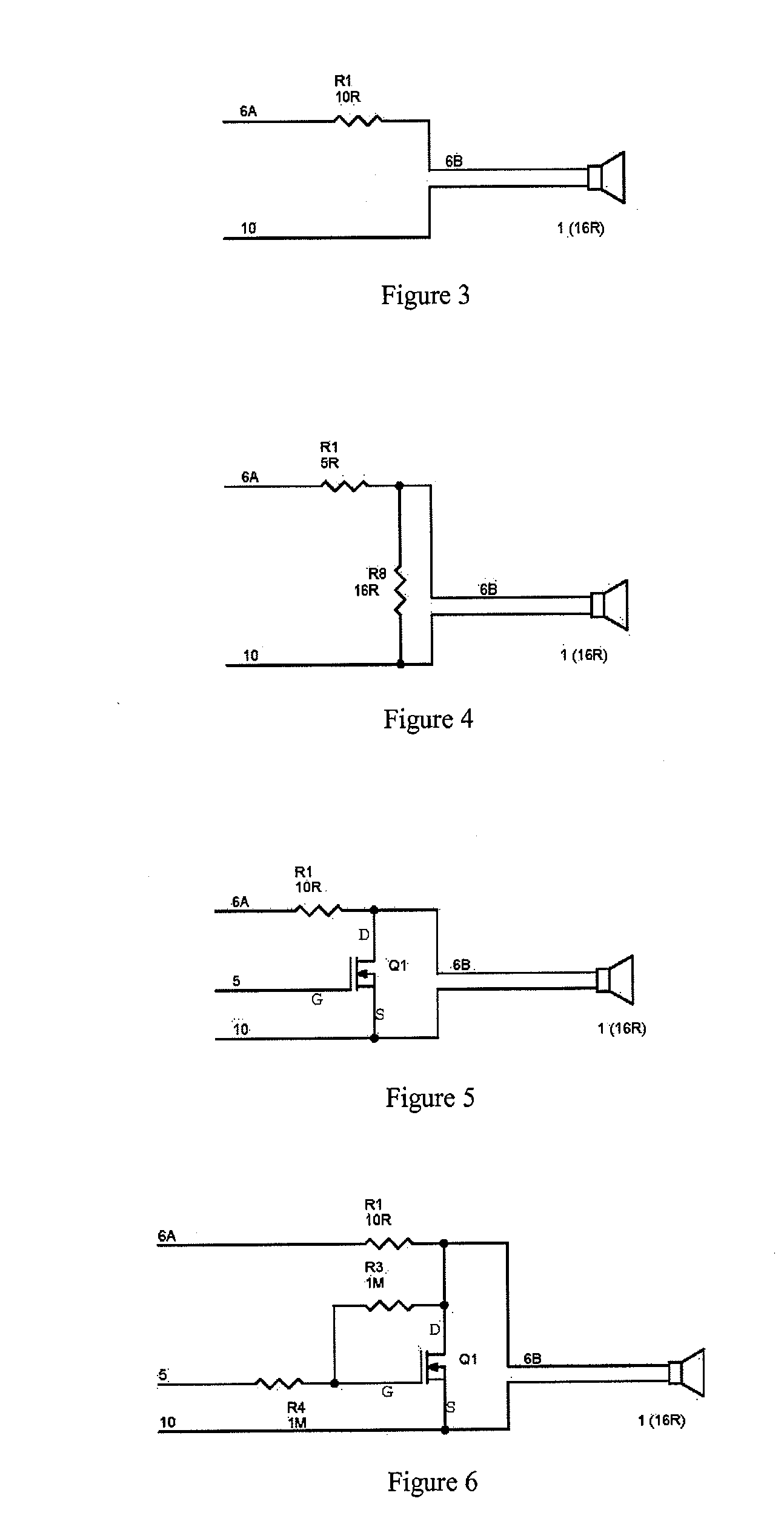
With only modest values of R1, considerable attenuation is possible with a
MOSFET, but relatively modest attenuation with a
JFET due to its limited RDS range.
However, even with the above
linearization scheme, JFETs and MOSFETs tend to introduce
distortion when RDS resistance is high.
If RDS was restricted to a range of 1:10 to minimise
distortion, this would significantly
restrict available attenuation.
This is usually a simple task, but becomes a significant challenge when the lowest possible
power consumption is required.
This and the use of relatively high-voltage amplifiers both tend to compromise micro-power applications.
Apart from the added complexity, such configurations have a limited negative
slew rate capability.
Where control speed is important, these schemes will have a similar problem with rising amplitude ramps being faster than falling amplitude in low-power applications.
This makes defining a particular control voltage to attain a particular level of attenuation very difficult, without resort to elaborate calibration and temperature compensation schemes.

