Multi-touch testing system and fixture thereof

a multi-touch testing and fixture technology, applied in the direction of testing manufactured objects, instruments, structural/machine measurement, etc., can solve the problems of complex structure of the overall testing fixture, inability to match the pressure of each test head on the panel with that of any other, and substantial space occupation of input interfaces, etc., to achieve the effect of simple structure of multi-touch testing fixtur

Inactive Publication Date: 2014-10-16
WISTRON CORP
View PDF6 Cites 16 Cited by
  • Summary
  • Abstract
  • Description
  • Claims
  • Application Information

AI Technical Summary

Benefits of technology

[0008]Another objective of the present disclosure is to provide a multi-touch testing system and the fixture thereof. The multi-touch testing fixture allows the pressure of each test head on the device under test to be identical to that of any other. In addition, the structure of the multi-touch testing fixture is simple.

Problems solved by technology

Nonetheless, these input interfaces occupy substantial spaces.
Because the test head are not connected to each other and are driven by different actuators, the pressure of each test head on the panel is not uniform with that of any other.
Besides, the structure of the overall testing fixture is complicated; it has larger volume and occupies large space.

Method used


Image

  • Multi-touch testing system and fixture thereof
  • Multi-touch testing system and fixture thereof
  • Multi-touch testing system and fixture thereof

Examples


third embodiment

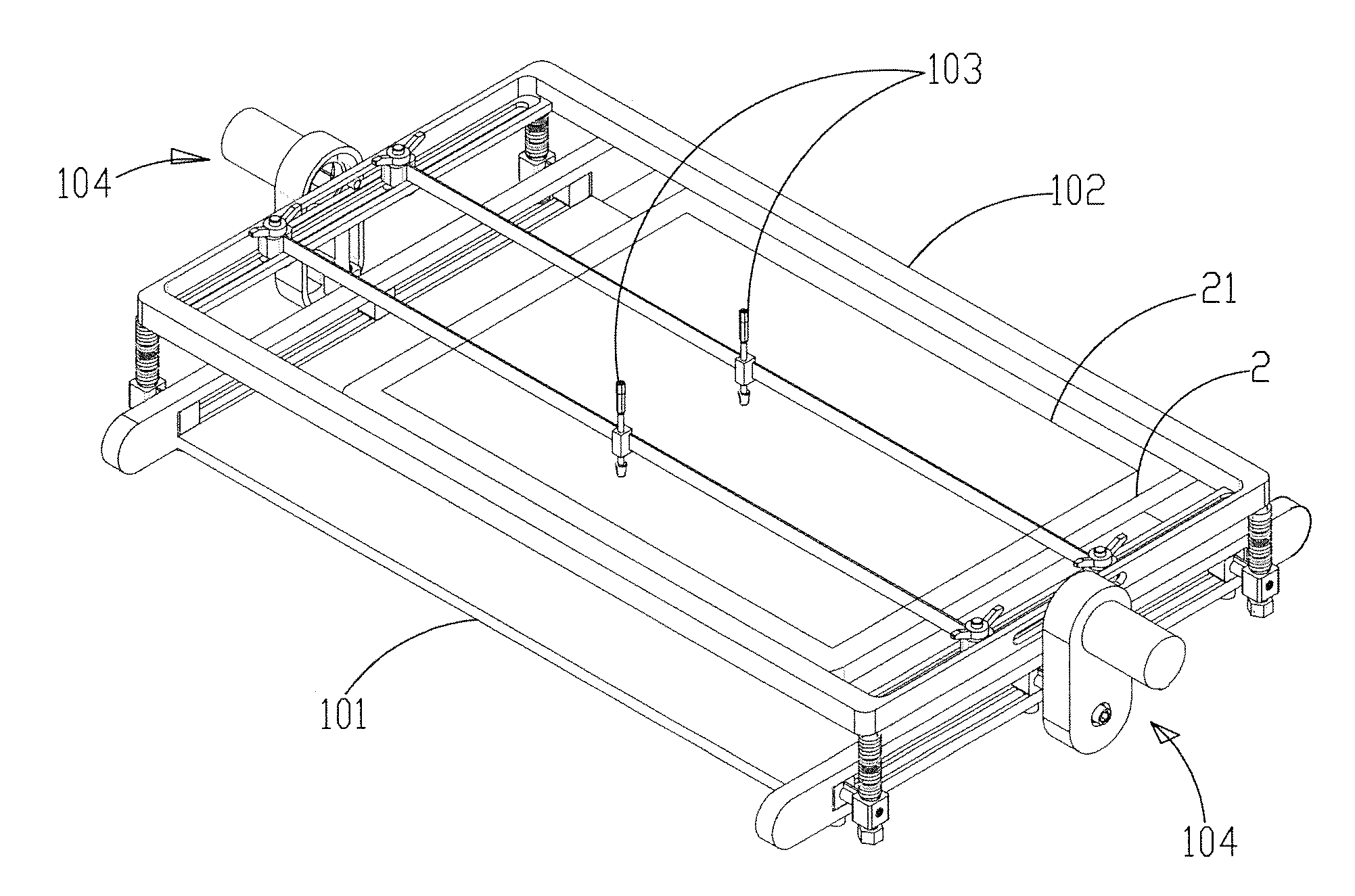
[0037]FIG. 11 shows a schematic diagram of the test head according to the present disclosure. As shown in the figure, each test head 103 comprises a main part 1031, a pressing part 1032, and an elastic part 1033. The main part 1031 has a first end 1031a and a second end 1031b. The first end 1031a has an accommodating trench 10311 extending to the second end 1031b. The pressing part 1032 penetrates the accommodating trench 10311 of the main part 1031; the elastic part 1033 is disposed in the accommodating trench and against the pressing part 1032. As the pressing part 1032 is drawn back into the accommodating trench 10311, the elastic part 1033 can make pressing part 1032 drawn back in the accommodating trench 10311 stick out and recover to its original position.

[0038]Besides, the main part 1031 has a third fastening part 10312. The third fastening part 10312 according to the present embodiment includes a pair of hooks 10313 opposing to each other. When the test had 103 is disposed a...

fourth embodiment

[0047]FIG. 14 shows a schematic diagram of the testing fixture according the present disclosure. As shown in the figure, the difference between the multi-touch testing fixture 10 according to the present embodiment and the one according to the previous embodiment is that the carrying platform 101 according to the present embodiment has a first carrying platform 1015 and a second carrying platform 1016. The first carrying platform 1015 is connected pivotally to the second carrying platform 1016. Thereby, the first carrying platform 1015 can flip with respect to the second carrying platform 1016. In addition, the carrying platform 101 according to the present embodiment further comprises an angle adjusting mechanism 1017 disposed at the junction between the first and second carrying platforms 1015, 1016 for controlling the flipping angle of the first carrying platform 1015 with respect to the second carrying platform 1016. The angle adjusting mechanism 1017 can be a gear mechanism; ot...


PUM

PropertyMeasurementUnit
conductiveaaaaaaaaaa
flipping angleaaaaaaaaaa
movementaaaaaaaaaa

Abstract

The present disclosure provides a multi-touch testing system and the fixture thereof. The multi-touch testing system comprises a multi-touch testing fixture and a monitoring device. The monitoring device is connected electrically with the multi-touch testing fixture and a device under test disposed at the multi-touch fixture. Thereby, the monitoring device activates the multi-touch testing fixture. The multiple test heads of the multi-touch testing fixture press the device under test simultaneously. Meanwhile, the device under test generates at least a signal. The monitoring device judges if the device under test passes the multi-touch test according to the signal. The pressure of each test head of the multi-touch testing fixture according to the present disclosure is identical to that of any other. In addition, the structure is simplified.

Description

FIELD OF THE DISCLOSURE[0001]The present disclosure relates generally to a touch testing system and the fixture thereof, and particularly to a multi-touch testing system and the fixture thereof.BACKGROUND OF THE DISCLOSURE[0002]In the history of the development of electronic equipment, the emergence of the input interfaces such as keyboards, mice, and touch pads solves the problem of input control. Nonetheless, these input interfaces occupy substantial spaces. For example, the keyboard occupies a half of the volume of a notebook computer or a cell phone. If the space for keyboards can be saved, the portability of products can be certainly improved. The most feasible method is to operate on the panel directly through touch controls. Touch panels surely can replace most functions of keyboards and mice; they also provide users with more intuitive and convenient operating experience. By replacing the keyboards with larger panels, lighter, thinner, and more fashionable designs can be fur...

Claims


Application Information

Patent Timeline
Patent Type & Authority Applications(United States)
IPC IPC(8): G01N3/08
CPCG01N3/08G01M99/007G01N3/40G01N2033/0078H04M1/24H04M2250/22
Inventor ZHANG, XIAO-BAOCHANG, SHOU-LUN
Owner WISTRON CORP
Why Eureka
Try Eureka