
Drum

a technology of drums and membranes, applied in the field of drums, can solve the problems of difficult uniform tension of the membrane member that constitutes the striking surface, and achieve the effects of uniform tension, easy displacement, and increased tension ratio

Inactive Publication Date: 2014-10-16
ROLAND CORP
View PDF8 Cites 3 Cited by
  • Summary
  • Abstract
  • Description
  • Claims
  • Application Information

AI Technical Summary

Benefits of technology

The present invention provides a drum that has a membrane member with a mesh. The drum achieves tension on the membrane by using an interval forming means and contact members that are placed in contact with the edge of the membrane. The contact members are displaced towards the center of the striking surface when the tension ring is reduced, which increases the length of the connection between the striking surface and the edge portion. This results in a uniform tension across the entire surface of the membrane. The use of multiple contact members at different positions along the circumferential direction of the connection portion further helps to achieve a uniform tension. This design makes the drum more flexible and easier to tension compared to traditional drums.

Problems solved by technology

The inventors have established that, for the aforementioned drum, it is difficult to apply uniform tension to the membrane member that constitutes the striking surface.

Method used


Image

  • Drum
  • Drum
  • Drum

Examples


first embodiment

[0036]The first embodiment of a drum of the present invention is explained below with reference to the figures.

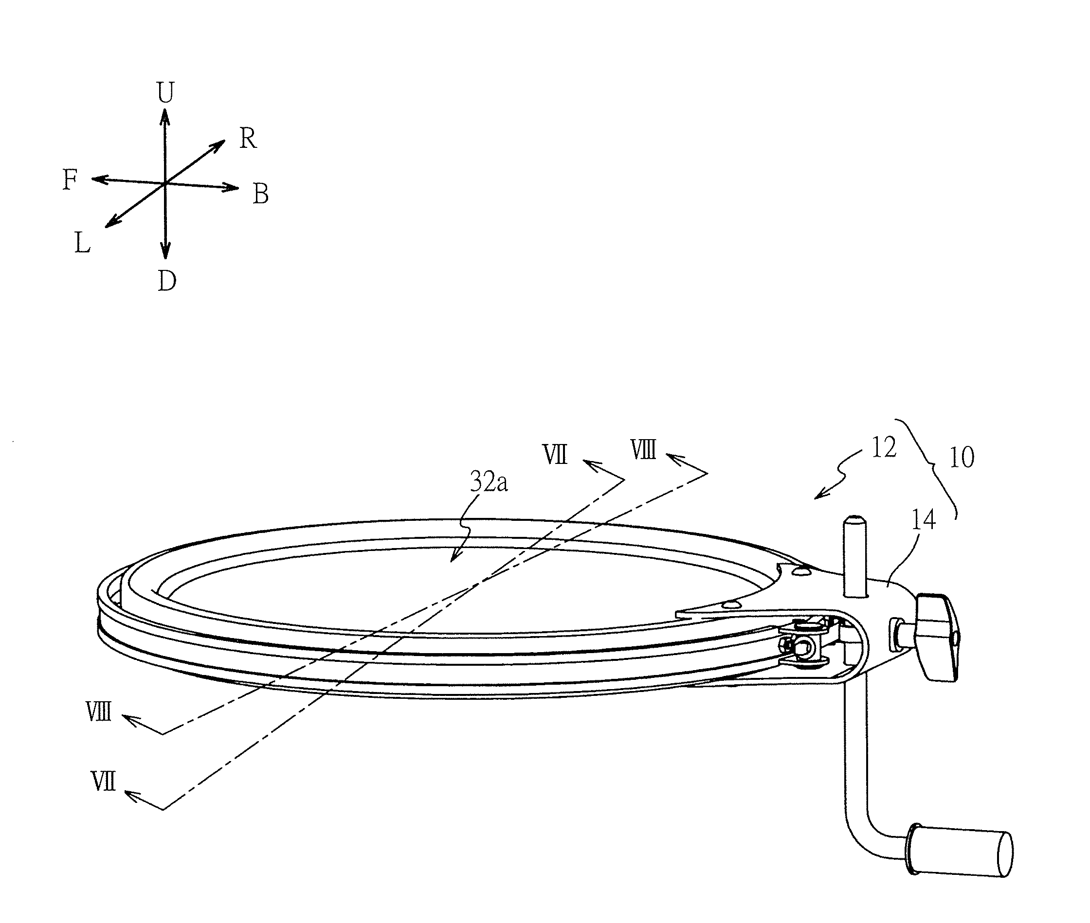
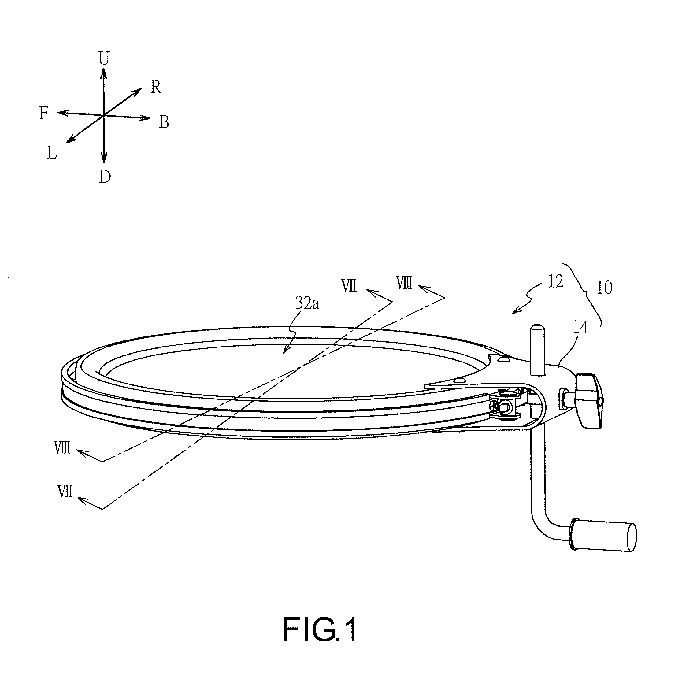
[0037]FIG. 1 is a schematic perspective view of a drum unit 10. As illustrated in this figure, the drum unit 10 includes a drum 12 and a support member 14 that supports the drum 12. The drum 12 is an electronic drum configured to sense the striking of a stick, not shown in this figure, and generate a sound that simulates a striking sound of an acoustic drum corresponding to the striking. A sensor and an information processing device that constitute the electronic drum may be implemented utilizing the conventional technology and thus will be not described in detail hereinafter.

[0038]In FIG. 1, a normal direction of a plane formed by a striking surface 32a of the drum 12 is at a vertical upper side of the figure, and this direction is defined as an upward direction U and the opposite direction is defined as a downward direction D. Then, in the plane of the striking surface 32...

second embodiment

[0091]Hereinafter, the second embodiment is described with reference to the figures, focusing on the difference between the first and the second embodiments.

[0092]This embodiment is the same as the first embodiment, except that this embodiment includes a tension ring 90 in place of the tension ring 70.

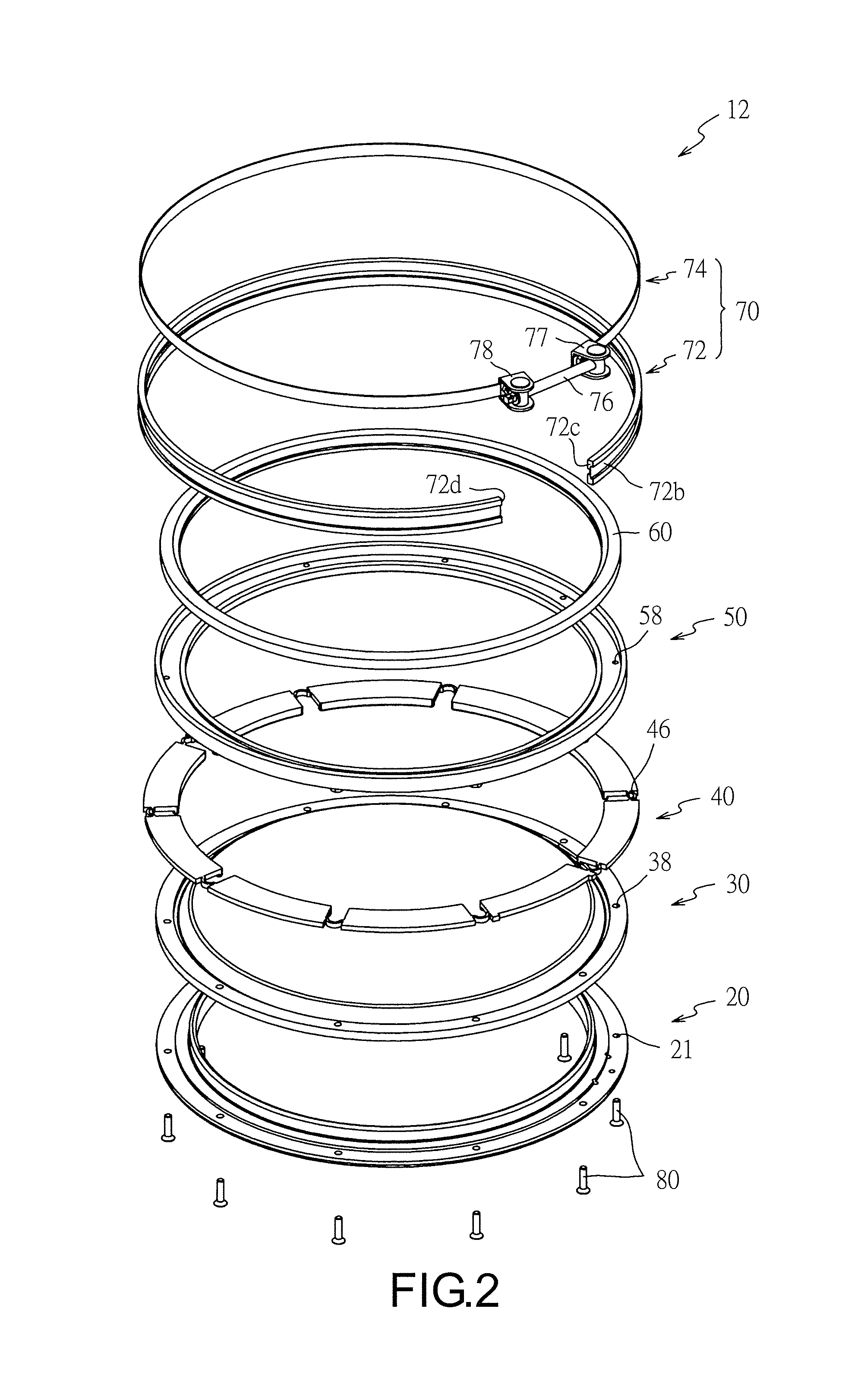
[0093]FIG. 10 illustrates a structure of the tension ring 90 of this embodiment. As shown in the figure, the tension ring 90 of this embodiment is an open-loop ring member made of aluminum. At two end portions of the tension ring 90, coupling members 97 and 98, which respectively correspond to the coupling members 77 and 78 of FIG. 2, are disposed. The coupling members 97 and 98 are coupled by a bolt 96. Then, by tightening the bolt 96, a distance between the coupling members 97 and 98 can be reduced. An inner circumferential groove 90a is formed on an inner circumference of the tension ring 90 for fitting the contact plates 40 (see FIG. 2).

Other Embodiments

[0094]The above illustrates ...


PUM


Abstract

A drum includes a fixing means for fixing an edge portion of the membrane member; an interval forming means for forming an interval between the edge portion, fixed by the fixing means, and the striking surface of the membrane member in a normal direction of a plane of the striking surface; and contact members in contact with a connection portion of the membrane member, which connects the edge portion and the striking surface. The contact members contact the connection portion respectively at different positions along a circumferential direction of the connection portion. The contact members are in contact with an inner side of the tension ring and are displaced toward a center of the striking surface as the diameter of the circle surrounded by the tension ring is reduced.

Description

CROSS-REFERENCE TO RELATED APPLICATIONS[0001]This application claims the priority benefit of Japan application serial no. 2013-084682, filed on Apr. 15, 2013. The entirety of the above-mentioned patent application is hereby incorporated by reference herein and made a part of this specification.BACKGROUND OF THE INVENTION[0002]1. Field of the Invention[0003]The present invention relates to a drum. More particularly, the present invention relates to a drum that is capable of applying uniform tension to a membrane member constituting a striking surface.[0004]2. Description of Related Art[0005]A drum of this type is found in the following Patent Literature 1, for example. In the drum, a member (bead 18) having a U-shaped cross-section is connected with end portions of a membrane member (skin 17). Then, the U-shaped member is disposed on a drum shell side surface and a tension ring (clamp ring 22) is tightened, so as to push the U-shaped member below a striking surface. Here, including t...

Claims


Application Information

Patent Timeline
Patent Type & Authority Applications(United States)
IPC IPC(8): G10D13/02
CPCG10D13/023G10D13/02G10D13/16
Inventor YOSHINO, KIYOSHI
Owner ROLAND CORP
Learn More