
System For Dynamic Control Of The Rolling Of The Guide Roller(s) For An Assembly For Guiding A Vehicle Along At Least One Rail

a technology of guide roller and assembly, which is applied in the direction of railway auxilary equipment, signalling indicators on vehicles, transportation and packaging, etc., can solve the problems of deviation of the means of the assembly, the part of the roller does not have the same stiffness characteristics as the flange, and the derailment should be anticipated

Active Publication Date: 2014-10-16
NEWTL
View PDF0 Cites 4 Cited by
  • Summary
  • Abstract
  • Description
  • Claims
  • Application Information

AI Technical Summary

Benefits of technology

This patent describes a system that can constantly monitor the movement of wheels or guide rollers on a guide rail. This helps to detect any deviation or change in the movement of the wheels, alerting an operator to potential guidance failures. The system is also able to detect excessive wear of the wheels, allowing for preventive maintenance. The sensors used in the system are robust and reliable, and the system does not require adjustment or calibration. This system provides a reliable and early warning of potential guidance failures, which can help to improve safety and reliability.

Problems solved by technology

But, in any case, this part of the roller does not have the same stiffness characteristics as the flange, whether or not it is made of the same material or is made of another material.
If the guide roller(s) come into rolling contact with its / their rolling path(s) via its / their flange(s) or its / their casing(s), the vehicle equipped with the guidance system continues to follow its trajectory; however, derailment should be anticipated.
Yet there are multiple causes for deviation of these means of rolling followed by departure from the guide rail.
This risk of derailment can be very high—particularly in urban areas in which the various routes and movements cause exposure to various forms of pollution and emissions, in addition to the debris and material carried by bad weather / unpredictable events and exception weather events.
But none of the passive anti-derailment systems give complete satisfaction with regard to the demanding safety requirements of urban transport for people.
When the guidance system derails—for example, in the case of a local discontinuation of the guide rail, the presence of an obstacle or unexpected object on the guide rail, ice, or whatever other cause—accidental lifting from the guidance system can occur.

Method used


Image

  • System For Dynamic Control Of The Rolling Of The Guide Roller(s) For An Assembly For Guiding A Vehicle Along At Least One Rail
  • System For Dynamic Control Of The Rolling Of The Guide Roller(s) For An Assembly For Guiding A Vehicle Along At Least One Rail
  • System For Dynamic Control Of The Rolling Of The Guide Roller(s) For An Assembly For Guiding A Vehicle Along At Least One Rail

Examples


Embodiment Construction

[0044]For reasons of simplification, the term “guide roller” will be used below. Obviously, by “roller(s)” one should understand very generally any rolling component that travels on a rail, including railway train wheels or tramway wheels.

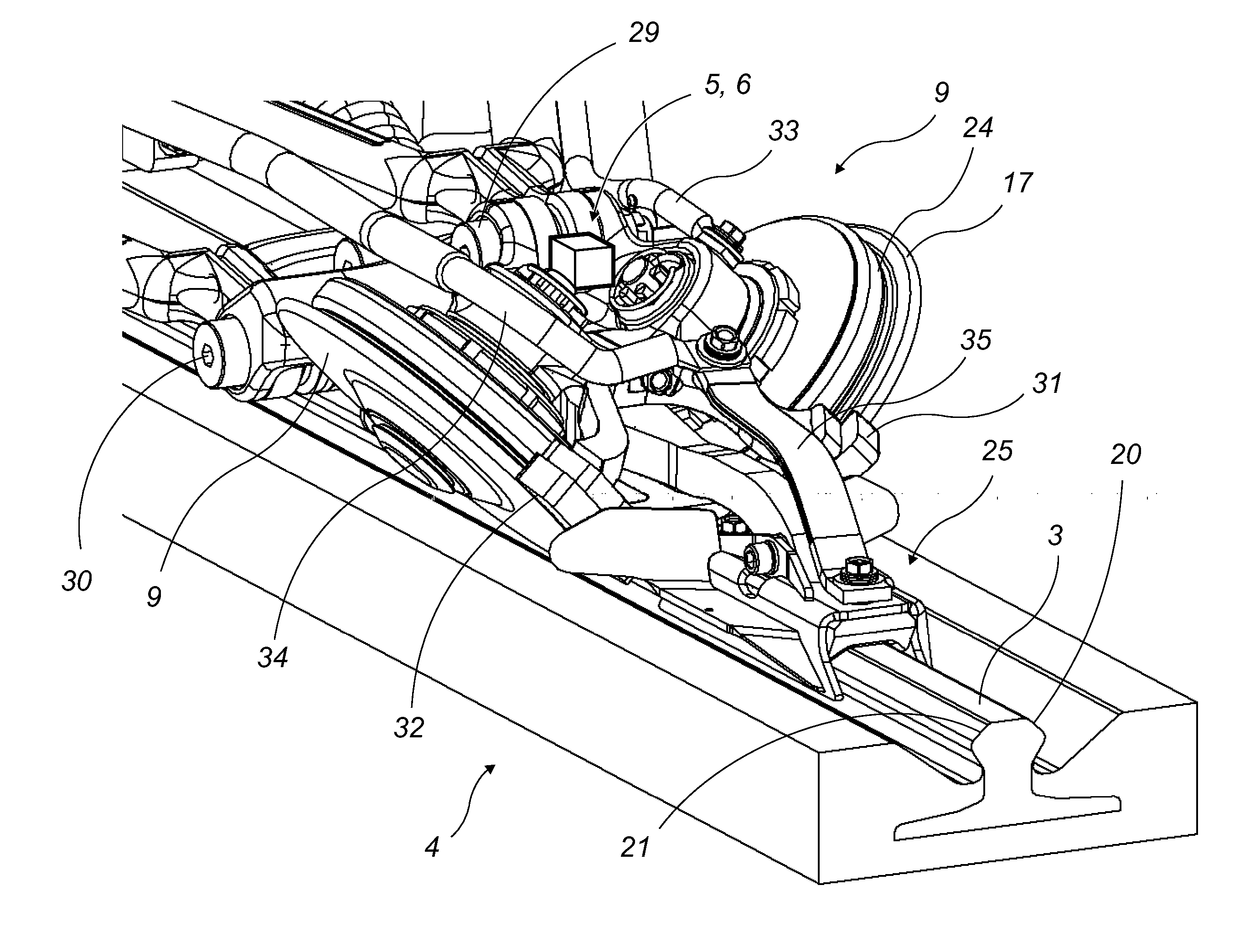
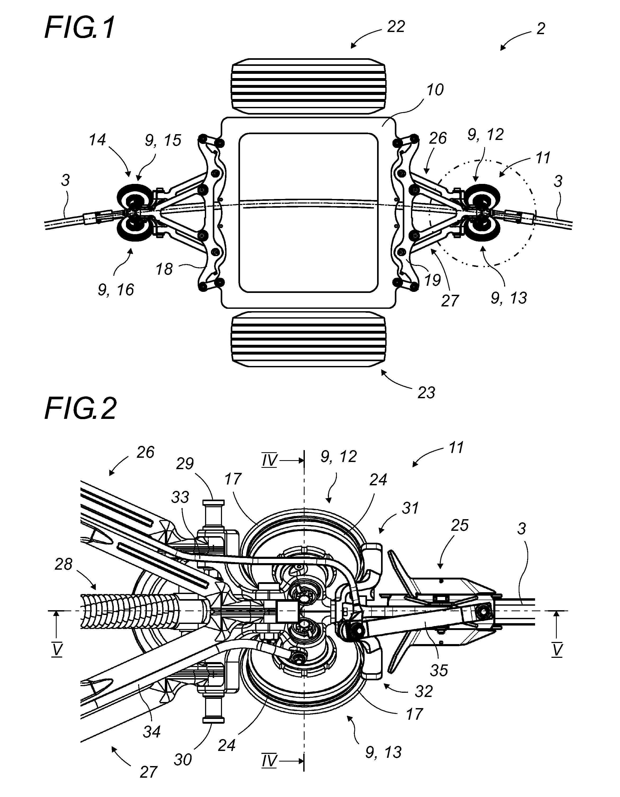
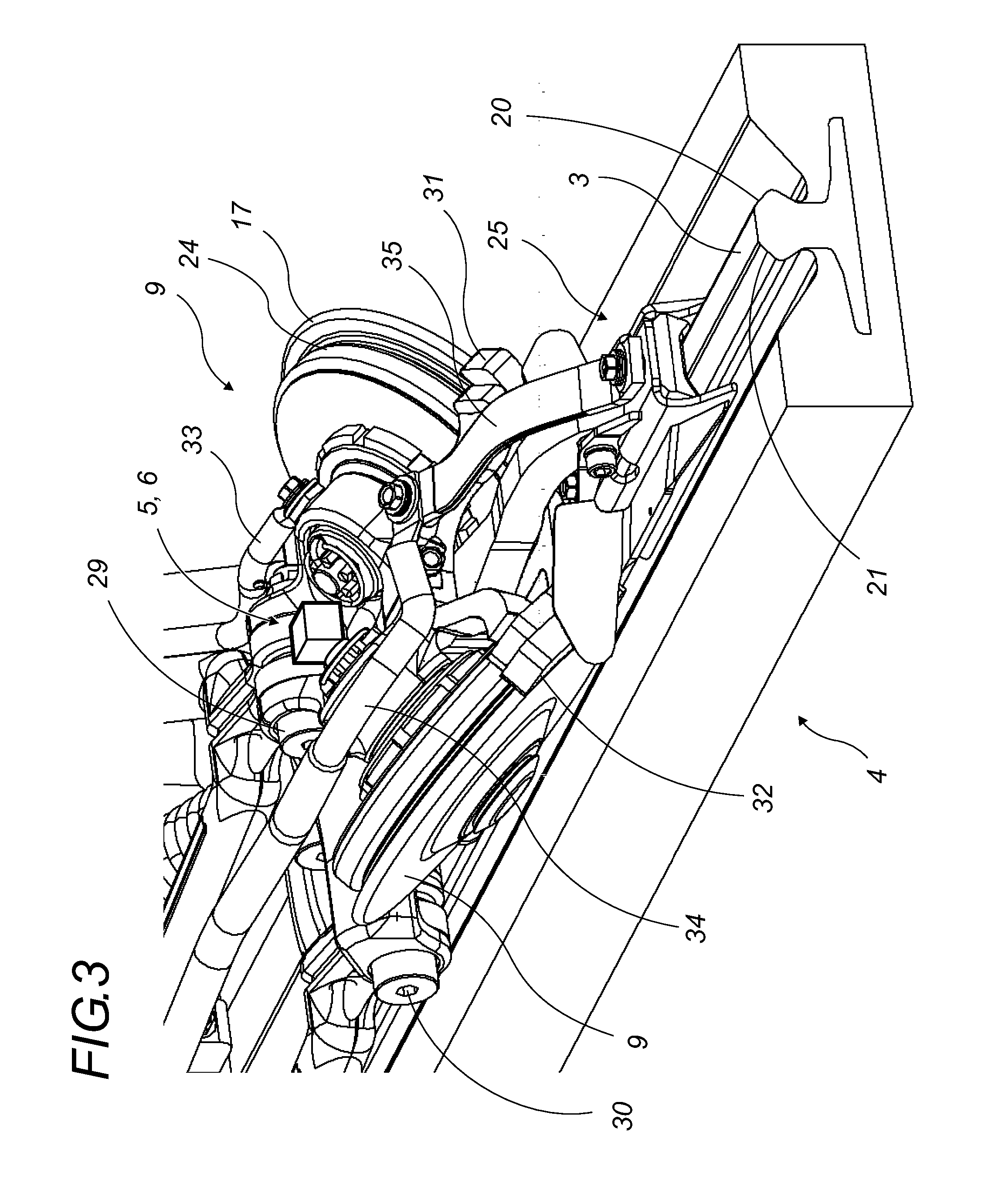
[0045]The invention herein proceeds from the general inventive idea by which one uses a dynamic monitoring system (1) on a guidance system (2) of a vehicle of whatever nature traveling along at least one guide rail (3), particularly on the ground (4), in which there is at least one vibrational sensor (5), for example, an accelerometer (6), and at least one proximity sensor (7), for example, an inductive sensor (8), carried or secured to this guidance system (2), close to at least one roller (9), or at least one pair of guide rollers (9), and one utilizes the signals from these sensors, (5), (7), to establish whether there is a guidance failure, the derailment status, and simple wearing of the tires of the guide rollers (9).

[0046]More particularly, ...


PUM


Abstract

A system of dynamic control of rolling on at least one guide rail for a guidance system of a vehicle along at least one guide rail, composed of at least one roller or at least one pair of guide rollers rolling along this guide rail, is characterized in that it incorporates a vibrational sensor located near at least one roller or at least one pair of guide rollers and a proximity sensor, and in that the signals transmitted by these sensors, or the circuits in which they are placed, are continually analyzed to establish a commencement of guidance failure, a guidance failure, a limit of wearing of or damage to the roller(s) or their tires. This invention is of interest to manufacturers of vehicles guided along at least one rail.

Description

FIELD OF THE INVENTION[0001]The invention pertains to a system for dynamic monitoring of the rolling of one or more rolling components for a system of guidance by rolling along at least one rail, particularly on the ground for a road vehicle, particularly a public transport vehicle.BACKGROUND OF THE INVENTION[0002]More particularly, this dynamic monitoring system combines the generation and recognition of a vibrational state and the indication of a difference in elevation of the rolling component(s) of the guidance system in relation to the guide rail(s), in view of supplying an information item concerning the derailment risk and status and the wearing of these rolling components, or of their tires.[0003]Such a detection can result from a measurement or a recognition of a vibrational state, and an inductive measurement from sensors located on the guidance system, to report any guidance failure, in order to prevent accidents subsequent to a derailment and, in any case, to minimize th...

Claims


Application Information

Patent Timeline
Patent Type & Authority Applications(United States)
IPC IPC(8): B61L15/00B61F9/00
CPCB61F9/005B61L15/0081B61K9/00B62D1/265B61F9/00B61B13/04
Inventor ANDRE, JEAN-LUC
Owner NEWTL
Learn More