Multi-axis integrated MEMS inertial sensing device on single packaged chip

a technology of inertial sensing and integrated mems, which is applied in the field of microelectromechanical systems, can solve the problems of increasing the cost of mems development, focusing on mems development, and reducing the development focus, so as to maximize the sensor size, optimize the design area of the chip, and improve the effect of sensor temperature performan

Active Publication Date: 2014-10-23
MCUBE INC
View PDF20 Cites 23 Cited by
  • Summary
  • Abstract
  • Description
  • Claims
  • Application Information

AI Technical Summary

Benefits of technology

[0008]In an embodiment, the present invention provides a structure of a multi-axis integrated MEMS inertial sensor device. The device can include an integrated 3-axis gyroscope and 3-axis accelerometer on a single chip, creating a 6-axis inertial sensor device. The structure is spatially with efficient use of the design area of the chip by adding the accelerometer device to the center of the gyroscope device. In a specific embodiment, the design architecture can be a rectangular or square shape in geometry, which makes use of the whole chip area and maximizes the sensor size in a defined area. The MEMS is centered in the package, which is beneficial to the sensor's temperature performance. Furthermore, the electrical bonding pads of the integrated multi-axis inertial sensor device can be configured in the four corners of the rectangular chip layout. This configuration guarantees design symmetry and efficient use of the chip area.
[0009]In a specific embodiment, the all portions of the gyroscope structure can be formed from a single mask layer and configured with a hollow middle portion. This single layer can incorporate each of the sensed gyro motions. X, Y, and Z axis sensors of the integrated gyroscope do not need to be formed separately, which reduces the number of steps in fabrication.
[0010]An optional design involves using a Z travel stop structure in a cap wafer to adjust damping performance in the central area of the chip, where the accelerometer device is disposed. This configuration can be used to mitigate a phenomenon called “accelerometer ringing”, which can be undesirable for various applications. Certain closed-loop feedback systems might be needed to control sensor ringing. By using the Z travel stop structure, the present design can alleviate “Accel ringing” during operation and allow a low damping gyroscope and a high damping accelerometer to coexist within a single package.

Problems solved by technology

Although highly successful, ICs and in particular MEMS still have limitations.
Similar to IC development, MEMS development, which focuses on increasing performance, reducing size, and decreasing cost, continues to be challenging.
Additionally, applications of MEMS often require increasingly complex microsystems that desire greater computational power.
Unfortunately, such applications generally do not exist.

Method used


Image

  • Multi-axis integrated MEMS inertial sensing device on single packaged chip
  • Multi-axis integrated MEMS inertial sensing device on single packaged chip
  • Multi-axis integrated MEMS inertial sensing device on single packaged chip

Examples


Embodiment Construction

[0015]The present invention is directed to MEMS (Micro-Electro-Mechanical-Systems). More specifically, embodiments of the invention provide methods and structures for improving integrated MEMS devices, including inertial sensors and the like. Merely by way of example, the MEMS device can include at least an accelerometer, a gyroscope, a magnetic sensor, a pressure sensor, a microphone, a humidity sensor, a temperature sensor, a chemical sensor, a biosensor, an inertial sensor, and others. But it will be recognized that the invention has a much broader range of applicability.

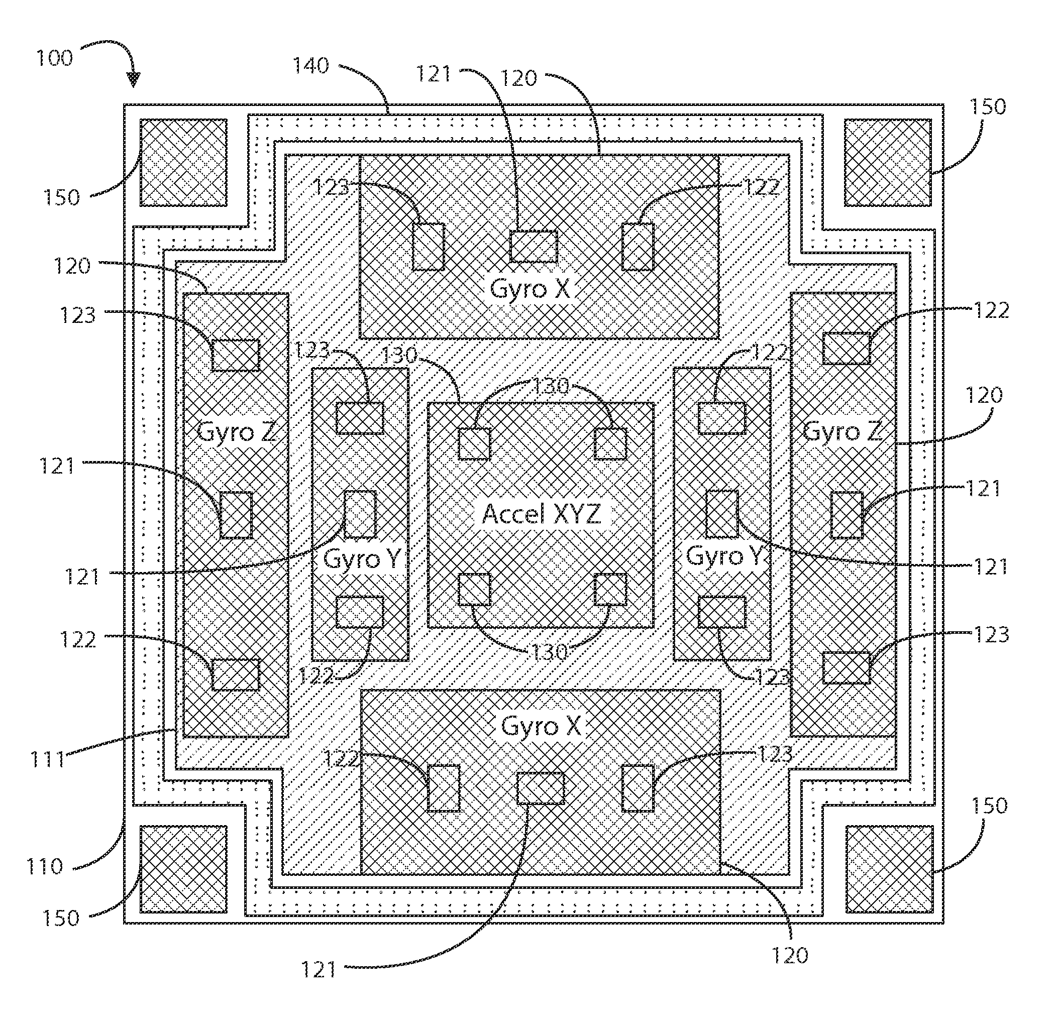
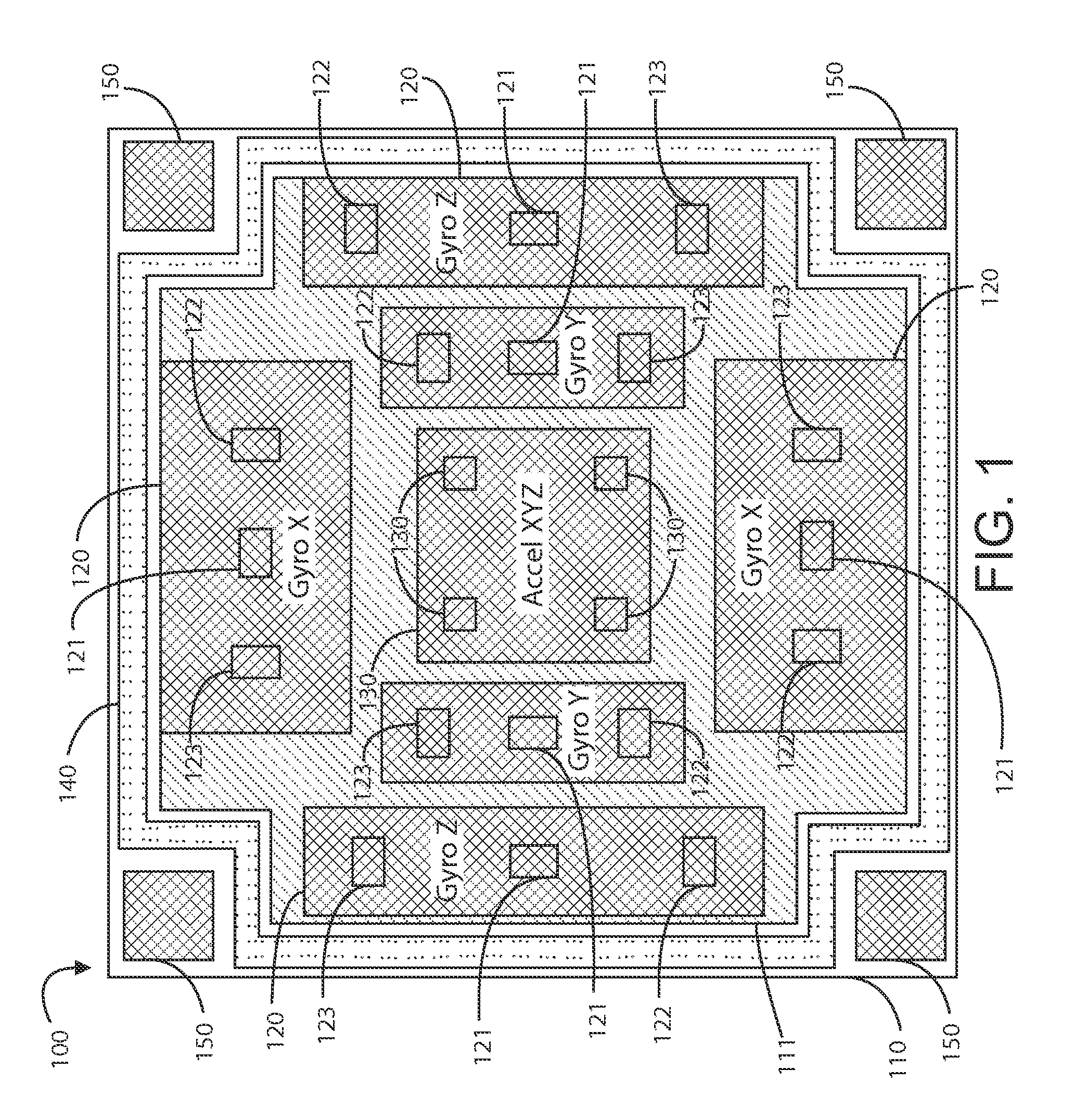
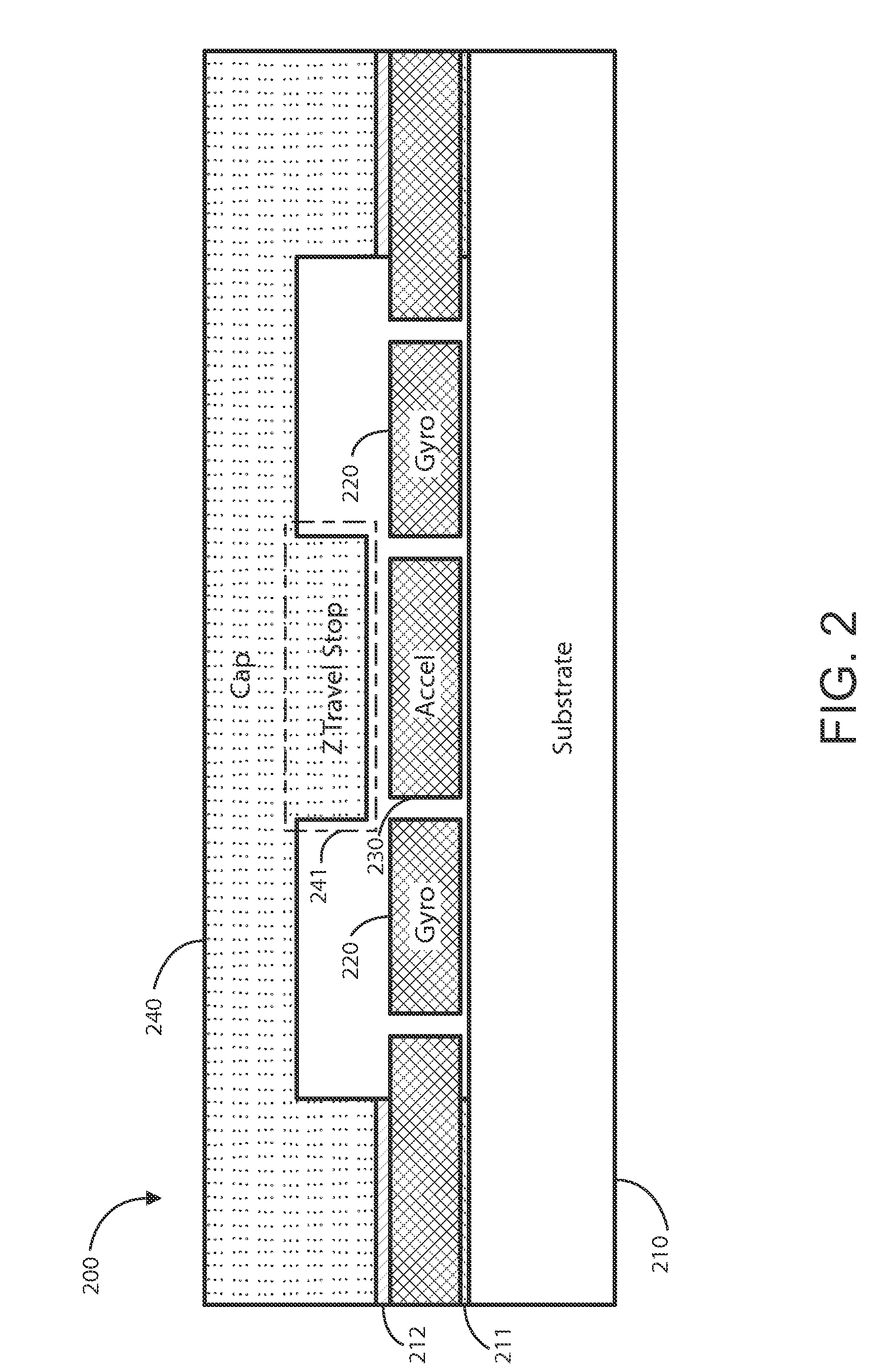
[0016]FIG. 1 is a simplified schematic diagram and FIG. 2 is a simplified cross-sectional diagram, both of which illustrate a multi-axis integrated MEMS inertial sensing device and according to an embodiment of the present invention.

[0017]As shown in FIG. 1, device 100 uses an architecture that allows a 3-axis gyroscope 120 and a 3-axis accelerometer 130 to be built in the same chip overlying substrate 110 and in...


PUM


Abstract

A multi-axis integrated MEMS inertial sensor device. The device can include an integrated 3-axis gyroscope and 3-axis accelerometer on a single chip, creating a 6-axis inertial sensor device. The structure is spatially with efficient use of the design area of the chip by adding the accelerometer device to the center of the gyroscope device. The design architecture can be a rectangular or square shape in geometry, which makes use of the whole chip area and maximizes the sensor size in a defined area. The MEMS is centered in the package, which is beneficial to the sensor's temperature performance. Furthermore, the electrical bonding pads of the integrated multi-axis inertial sensor device can be configured in the four corners of the rectangular chip layout. This configuration guarantees design symmetry and efficient use of the chip area.

Description

CROSS-REFERENCES TO RELATED APPLICATIONS[0001]The present application claims priority to and incorporates by reference, for all purposes, the following pending patent applications: U.S. Provisional App. 61 / 757,085, filed Jan. 25, 2013, (Attorney Docket No.: 92580-010300US-864683), and U.S. Provisional App. 61 / 757,088, filed Jan. 25, 2013, Attorney Docket No.: (92580-010400US-864686).BACKGROUND OF THE INVENTION[0002]The present invention is directed to MEMS (Micro-Electro-Mechanical-Systems). More specifically, embodiments of the invention provide methods and structure for improving integrated MEMS devices, including inertial sensors and the like. Merely by way of example, the MEMS device can include at least an accelerometer, a gyroscope, a magnetic sensor, a pressure sensor, a microphone, a humidity sensor, a temperature sensor, a chemical sensor, a biosensor, an inertial sensor, and others. But it will be recognized that the invention has a much broader range of applicability.[000...

Claims


Application Information

Patent Timeline
Patent Type & Authority Applications(United States)
IPC IPC(8): G01C19/56G01P15/02
CPCG01P15/02G01C19/56G01C19/5783G01P15/18G01P2015/088G01P2015/0871G01P1/003B81B2201/0242B81B2201/0235B81B7/0038
Inventor LEE, TERRENCEZHANG, WENHUASRIDHARAMURTHY, SUDHEERYONEOKA, SHINGO
Owner MCUBE INC
Why Eureka
Try Eureka