
Switch monitoring and railway line management

a technology of switch monitoring and railway line, applied in the direction of rail switches, transportation and packaging, ways, etc., can solve the problems of high failure frequency, short service life, complicated structure, etc., and achieve the effect of reducing the number of incidents due to switch failures

Inactive Publication Date: 2014-10-23
IBM CORP
View PDF16 Cites 10 Cited by
  • Summary
  • Abstract
  • Description
  • Claims
  • Application Information

AI Technical Summary

Benefits of technology

The present invention provides a switch monitoring scheme that can identify the state of a switch, which helps predict switch failure in a line management scheme. As a result, different measures can be taken based on the monitored state of the switch to reduce accidents due to switch failure.

Problems solved by technology

The switch has features such as large number (number of switches in a station larger than medium size often approaches thousands of groups, for example), complicated structure, short service life, high failure frequency, high maintenance cost etc.
Switch failure is divided into indoor failure and outdoor failure, the former is primarily the failure of motor per se and the latter is the failure while the switch is pulled or in use.
Generally, since switch device is exposed at outdoor for a long period of time, it is frequently interfered by outside factors and its rate of failure is much higher than that of indoor switch.
Switch failure will bring severe property loss and human casualty; however, it is very difficult to accurately estimate and predict a switch failure in practice, it is thus difficult to take measures to prevent an accident from happening before a switch failure.
Human maintenance and inspection on switch is manpower consuming, and often it is difficult to be conducted in day time due to time limit.

Method used


Image

  • Switch monitoring and railway line management
  • Switch monitoring and railway line management
  • Switch monitoring and railway line management

Examples


Embodiment Construction

[0028]The terminology used herein is for the purpose of describing particular embodiments only and is not intended to be limiting of the invention. As used herein, the singular forms “a”, “an” and “the” are intended to include the plural forms as well, unless the context clearly indicates otherwise. It will be further understood that the terms “comprises” and / or “comprising,” when used in this specification, specify the presence of stated features, integers, steps, operations, elements, and / or components, but do not preclude the presence or addition of one or more other features, integers, steps, operations, elements, components, and / or groups thereof.

[0029]The corresponding structures, materials, acts, and equivalents of all means or step plus function elements in the claims below are intended to include any structure, material, or act for performing the function in combination with other claimed elements as specifically claimed. The description of the present invention has been pr...


PUM


Abstract

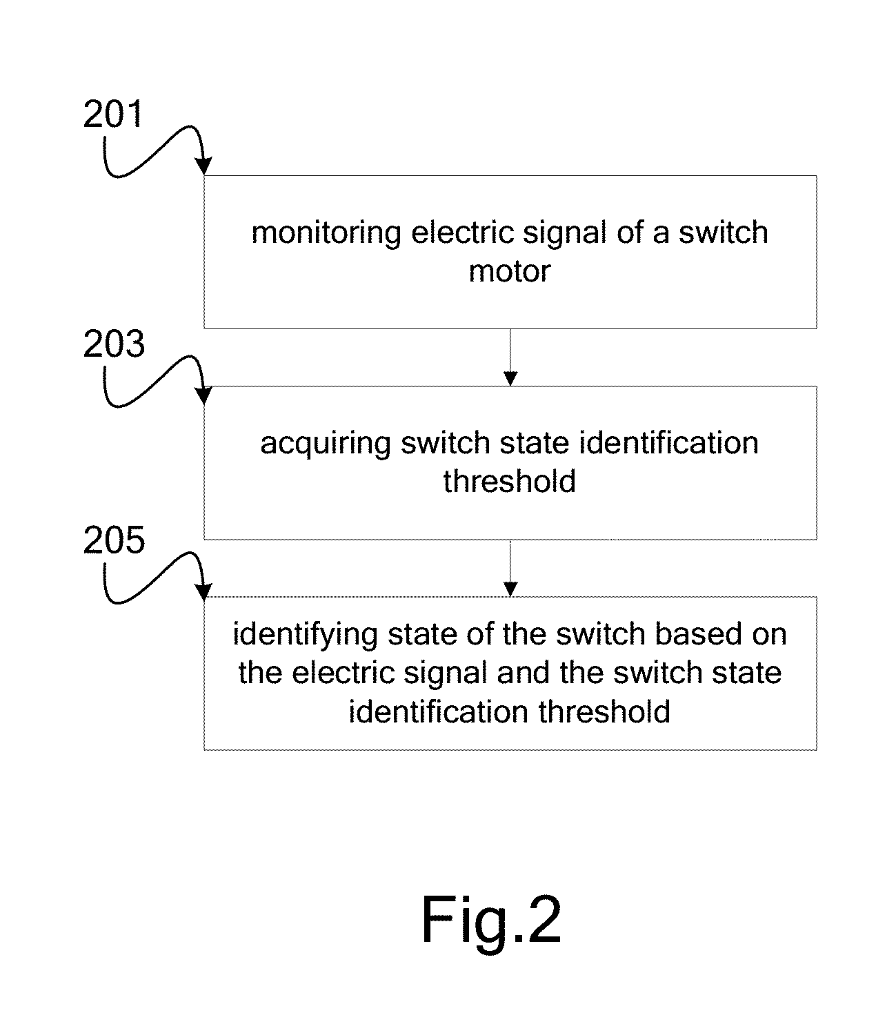
A switch monitoring method and a switch monitoring system, a railway line management method and a railway line management system are provided. Electric signal of a switch motor during pulling of the switch can effectively reflect status of the switch, when the switch is in a stable state, electric signal of its motor is very steady during pulling of a switch of the switch; however, when the switch is in an unstable state, there will be different degrees of fluctuation in electric signal of its motor during pulling of the switch. Thus, the invention may be used to identify state of a switch by monitoring electric signal of a switch motor (201,203,205), and further take different measures based on different states of the switch (401,403,405). With these measures, accidents due to switch failure may be effectively reduced, and train delay time may also be reduced through proper line management.

Description

TECHNICAL FIELD OF THE INVENTION[0001]The present invention generally relates to a method and system of managing railway, and more particularly, the present invention relates to a switch monitoring method and a switch monitoring system, a railway line management method and a railway line management system.BACKGROUND OF THE INVENTION[0002]Switch is a line connection device that transfers a locomotive from one line to another and is widely used in railway, mine road. Pass-through capability of a line can be fully exploited with the help of switch. Switch is a huge family, the most common one is ordinary single switch, which is composed of three units: converter, connecter, frog and guard rail. The converter comprises basic rail, point rail and converter mechanism. Besides single switch, there are also double switch, triple switch and multiple switch (multiple cross switch) and so on. The switch has features such as large number (number of switches in a station larger than medium size ...

Claims


Application Information

Patent Timeline
Patent Type & Authority Applications(United States)
IPC IPC(8): B61L23/04
CPCB61L23/04B61L5/102B61L27/16B61L27/53E01B7/20E01B35/12
Inventor DUAN, NINGHU, KELI, LIMO, WEN TINGSUN, WEISUN, XIWANG, FENG JUAN
Owner IBM CORP
Learn More