Image pickup apparatus

a technology of image pickup and image data, which is applied in the direction of color television details, television system details, television systems, etc., can solve the problems of long time period required to read out signals, loss of continuity of interest areas in output images, and difficulty in image restoration, so as to reduce the blank areas of output image data

Inactive Publication Date: 2014-10-23
CANON KK
View PDF15 Cites 1 Cited by
  • Summary
  • Abstract
  • Description
  • Claims
  • Application Information

AI Technical Summary

Benefits of technology

[0009]An object of the present invention is to reduce blank areas of output image data as much as possible when partial readout areas are specified, and to generate an image signal in which partial readout areas may be easily found, in a partial readout capable image pickup apparatus.
[0011]According to one embodiment of the present invention, in the partial readout capable image pickup apparatus, the blank areas of output image data can be reduced as much as possible so that reductions in rate of data sent to an external portion from the image pickup apparatus can be kept to a minimum, and the image signal in which the partial readout areas are easily found can be generated while maintaining the shapes of images read out from the plurality of interest areas.

Problems solved by technology

When such an image pickup apparatus is used to take moving images and read out signals from all of the pixels in the pixel arrays, the number of pixels is large, and hence a long period of time is necessary to read out the signals from the pixel arrays.
In particular, for cases where there is a plurality of interest areas and the horizontal and vertical positions of each interest area differ, continuity of the interest areas in an output image may be lost.
It thus becomes difficult to perform image restoration after receiving image data.

Method used


Image

  • Image pickup apparatus
  • Image pickup apparatus
  • Image pickup apparatus

Examples


first embodiment

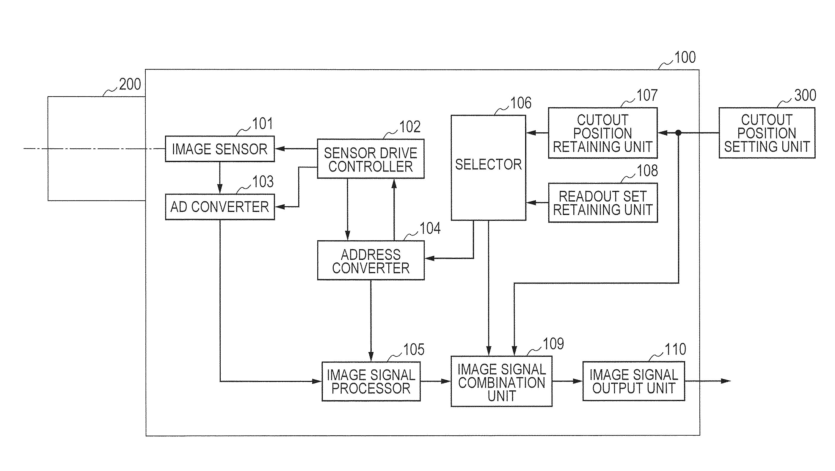
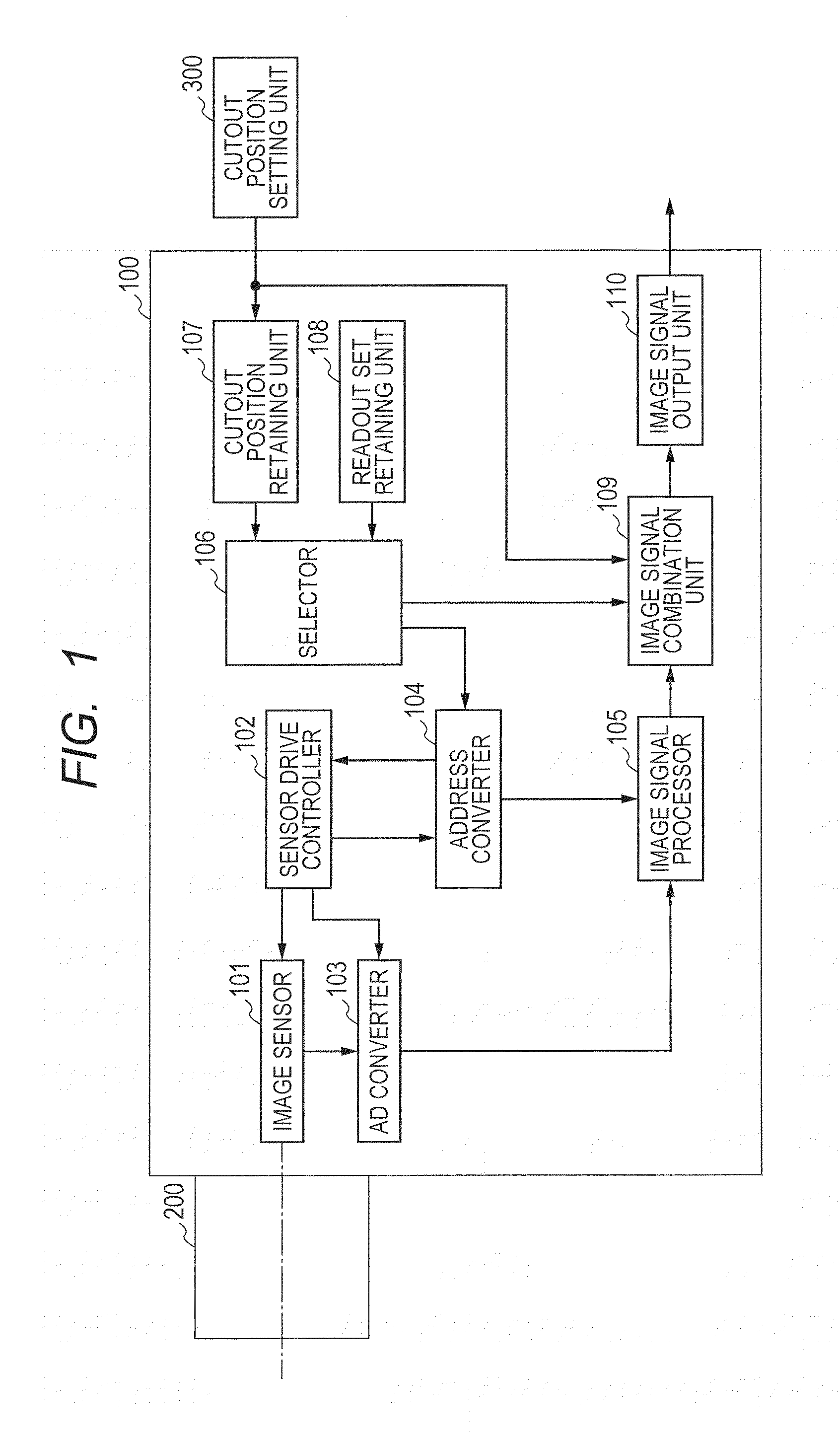
[0043]FIG. 1 is a configuration diagram of an image pickup apparatus according a first embodiment of the present invention. An image pickup apparatus 100 includes an image pickup system including an image sensor 101, and performs image pickup processing by a sensor drive controller 102, an AD converter 103, and an address converter 104. A lens 200 is configured in an external portion of the image pickup apparatus 100, and light flux that passes through the lens 200 forms an image on the image sensor 101 of the image pickup apparatus 100. The lens 200 includes a stop, a focus lens group, and the like (not shown). Further, a zoom lens group including the lens 200 may have a variable or a fixed focal length.

[0044]The sensor drive controller 102 controls an electric charge accumulation operation and a readout operation of the image sensor 101. When the sensor drive controller 102 performs the image pickup processing of the image sensor 101, an image pickup signal is output from the imag...

second embodiment

[0085]In the first embodiment, an example has been described in which each of the interest areas is taken together as one block, (Xmin, Ymin) and (Xmax, Ymax) are found from all the coordinates of the interest areas, and conformity of the positional relationships between the interest areas is maintained by reducing the number of pixels read out in the horizontal and vertical directions. In this embodiment, an example is shown where unnecessary data is further reduced even more than the output results of the first embodiment of FIG. 13. Specifically, an example is shown where the amount of image signal data is further reduced from the interest areas and other data in the image signals illustrated in FIG. 13.

[0086]FIG. 16 illustrates a configuration diagram of an image pickup apparatus in this embodiment. The image pickup apparatus of this embodiment is similar to the configuration of the first embodiment illustrated in FIG. 1 except for an address convertor 120, and therefore explana...

third embodiment

[0109]The second embodiment illustrates an example where lines that are not included in any interest area are extracted, the set of lines that are included in each interest area are divided into a plurality of groups, and an optimal readout method is implemented for ImgA and ImgB, and for ImgC and ImgD, thus reducing readout time. That is, the second embodiment shows an optimal example of reducing readout data between interest areas in the horizontal direction. This embodiment shows a method of reducing data between interest areas in the vertical direction.

[0110]FIG. 24 illustrates a configuration diagram of an image pickup apparatus in this embodiment. The image pickup apparatus of this embodiment includes a memory (pixel signal memory) 400 and an image signal combination unit 500 in addition to the configuration shown by the second embodiment. The memory 400 stores pixel signals output from the image signal processor 105, and performs output to the image signal combination unit 50...


PUM


Abstract

An image pickup apparatus includes: an interest area setter configured to input a signal in order to set plurality of interest areas within an image pickup area of an image sensor; a readout area setter configured to set a readout area to read out an image signal from the image sensor so as to maintain shapes of the respective interest areas in an image formed by an image signal to be output; a sensor readout controller configured to control readout of a pixel signal of the readout area from the image sensor; and an output signal generator configured to generate the image signal to be output based on the pixel signal read out by the sensor readout controller.

Description

BACKGROUND OF THE INVENTION[0001]1. Field of the Invention[0002]The present invention relates to an image pickup apparatus, and more particularly, to an image pickup apparatus having a partial readout function.[0003]2. Description of the Related Art[0004]In production lines of factories, image pickup apparatus for image input have been used instead of visual inspection by a human inspector. Those image pickup apparatus are also called machine vision cameras, which are used for inspecting various components and products together with a computer or a digital input / output apparatus. In recent years, in order to improve the inspection accuracy, an image pickup apparatus including ten-million or more pixels has been used.[0005]When such an image pickup apparatus is used to take moving images and read out signals from all of the pixels in the pixel arrays, the number of pixels is large, and hence a long period of time is necessary to read out the signals from the pixel arrays. This reduce...

Claims


Application Information

Patent Timeline
Patent Type & Authority Applications(United States)
IPC IPC(8): H04N5/353H04N5/376H04N5/217H04N5/378
CPCH04N5/353H04N5/2173H04N5/3765H04N5/378H04N25/443H04N25/745H04N25/75
Inventor ISOBE, SHINGO
Owner CANON KK
Why Eureka
Try Eureka