Method of generating a smooth image from point cloud data

a technology of point cloud data and smooth image, which is applied in image data processing, instruments, electric digital data processing, etc., can solve the problems of distorted point cloud, little success, and inaccurate representation of the true dimensions of the actual object in the scan file obtained from the 3d scanner

Active Publication Date: 2014-10-23
ASKAN YOLDAS
View PDF2 Cites 92 Cited by
  • Summary
  • Abstract
  • Description
  • Claims
  • Application Information

AI Technical Summary

Benefits of technology

[0008]In accordance with the invention, a method for processing an array of pixels in a point cloud, comprising calculating local error limits for each distance value for each pixel in the processed point cloud data set is provided. The method further comprises determining the error bar. One begins a distance value adjusting loop by for each pixel in the processed point cloud data set by calculating the difference between the distance value in the pixel of the point cloud data set being processed and each of the neighboring pixels or the most suitable neighboring pixel distance value is determined whether the difference is within the range defined by the error bar. It the difference is not within the error bar, the distance value is changed for the pixel being processed by a small fraction while keeping the new distance value within the range defined by the original distance value for the pixel being processed plus or minus the error bar. If the difference is within the error bar the distance value in the pixel being processed is replaced by a weighted average value. The number of neighboring pixels with their distance values within the error bar for the pixel being processed is counted and if the count is greater than a predetermined threshold, average the counted distance values and substitute the average for the pixel distance value, but if the count is below the threshold leave the pixel distance value unchanged. It is determined whether loop exit criteria have been met and if loop exit criteria have not been net beginning the loop again, and if loop exit criteria have been met, terminating the loop.

Problems solved by technology

Although 3D laser scanners are improving in quality, the point cloud scan files obtained from 3D scanners do not accurately represent the true dimensions of the actual object due to various types of noise such as statistical noise and false scatter points.
Laser scanner technicians have developed methods using registration markers in various forms or shapes known within the software of the laser scanner to aid in accurate measurement with little success.
Even with the use of these objects, such as a sphere designed to be fully recognized by the scanner, the point cloud is not accurately represented and, instead, is distorted.
Aside from attempts to fine tune the laser scanners themselves, when tools designed to measure between scan points are utilized, they also fail to show the full expected field of view and oftentimes deviate by a significant amount.
It is recognized that some 3D images need smoothing in order to take accurate measurements of an object; however, these smoothing techniques distort and / or diminish the density of the original scan data.
Other attempts do not rid the image of statistical noise to a high enough degree to be useful for small measurements.
Another shortfall of typical 3D scans is the amount of scatter points and surface roughness included in scan files which mask the true shape of the object being measured.
For example, if minute measurements are needed to monitor the deformation of an object to determine whether the structural integrity has been compromised for engineering purposes, this cannot be done to a high degree of certainty with various forms of noise present and, currently, the software and techniques for tuning the laser scanners do not provide adequate images.

Method used


Image

  • Method of generating a smooth image from point cloud data
  • Method of generating a smooth image from point cloud data
  • Method of generating a smooth image from point cloud data

Examples


Embodiment Construction

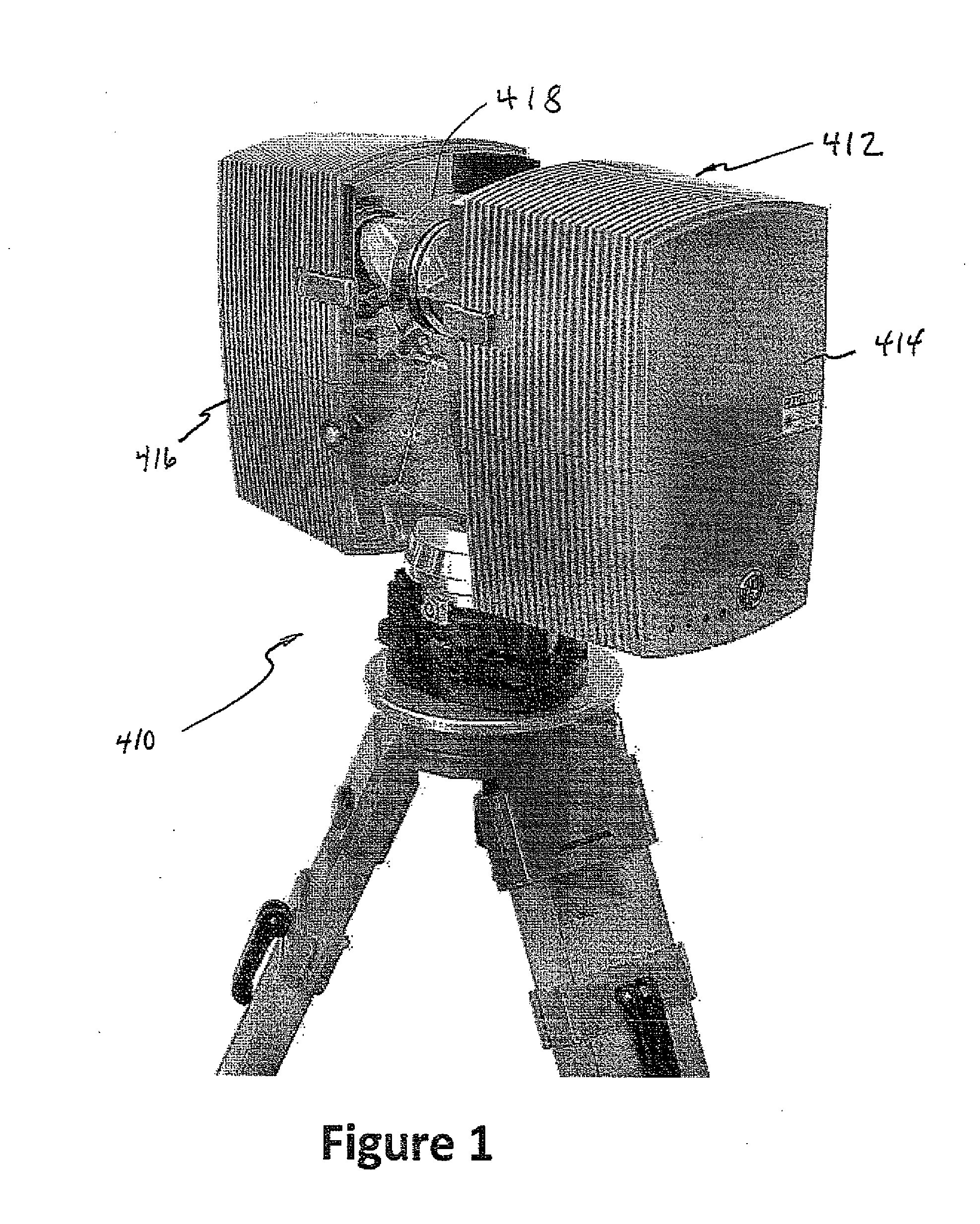
[0032]Referring to FIG. 1, an image of a typical 3D spatial laser scanner 410 with a rotating head 414 comprised of two rectangular blocks 412 and 416 between which a wedged mirror 418 rotates is shown. The scanner aims a laser beam in a systematic mode of operation by the rotation of the head of the scanner in increments between two pan angle limits. The width of the scan field of view is obtained by the rotation of the head while the height of the scan field is obtained by a mirror that flips vertically. The distance value measurement is recorded as the distance between the origin of the laser and the surface of the first object within its path.

[0033]The systematic emission of millions of laser beams allows the 3D laser scanner to collate accurate measurement of distances to objects producing a 3D model often referred to as a “Point Cloud.” A typical point cloud contains “noise” which constitutes scatter points and surface roughness. Scatter points, usually observed when the angle...


PUM


Abstract

A method for processing an array of pixels in a point cloud, comprises calculating local error limits for each distance value for each pixel in the processed point cloud data set. One may then determine the error bar. One begins a distance value adjusting loop by for each pixel in the processed point cloud data set by calculating the difference between the distance value in the pixel of the point cloud data set being processed and each of the neighboring pixels or the most suitable neighboring pixel distance value is determined whether the difference is within the range defined by the error bar. It the difference is not within the error bar, the distance value is changed for the pixel being processed by a small fraction while keeping the new distance value within the range defined by the original distance value for the pixel being processed plus or minus the error bar. If the difference is within the error bar the distance value in the pixel being processed is replaced by a weighted average value. The number of neighboring pixels with their distance values within the error bar for the pixel being processed is counted and if the count is greater than a predetermined threshold, average the counted distance values and substitute the average for the pixel distance value, but if the count is below the threshold leave the pixel distance value unchanged. It is determined whether loop exit criteria have been met and if loop exit criteria have not been met beginning the loop again, and if loop exit criteria have been met, terminating the loop.

Description

CROSS REFERENCE TO RELATED APPLICATIONS[0001]This application is a continuation-in-part of U.S. patent application Ser. No. 13 / 532,691 filed Jun. 25, 2012, the disclosure of which is hereby incorporated by reference thereto.TECHNICAL FIELD[0002]The invention relates to apparatus and methods for generating, for example in three dimensions, a surface contour representation of a surface or portion thereof from a three dimensional scan file forming a point cloud data set.STATEMENT REGARDING FEDERALLY SPONSORED RESEARCH OR DEVELOPMENT[0003](Not applicable)BACKGROUND OF THE INVENTION[0004]Although 3D laser scanners are improving in quality, the point cloud scan files obtained from 3D scanners do not accurately represent the true dimensions of the actual object due to various types of noise such as statistical noise and false scatter points.[0005]Laser scanner technicians have developed methods using registration markers in various forms or shapes known within the software of the laser sca...

Claims


Application Information

Patent Timeline
Patent Type & Authority Applications(United States)
IPC IPC(8): H04N1/38
CPCH04N1/38G06T5/002G06T1/60G06T5/20G06T7/73G06T17/00G06T2200/08G06T2207/10028
Inventor ASKAN, YOLDAS
Owner ASKAN YOLDAS
Why Eureka
Try Eureka