Methods and Apparatus for Selectively Combining Particulate Material

a technology of selective combining and particulate material, which is applied in the direction of additive manufacturing process, electric/magnetic/electromagnetic heating, manufacturing tools, etc., can solve the problems of preventing the progress of the build, poor part quality, and failure of the build, so as to increase reduce the energy provided to the sintered portion

Active Publication Date: 2014-10-23
LOUGHBOROUGH UNIV
View PDF4 Cites 96 Cited by
  • Summary
  • Abstract
  • Description
  • Claims
  • Application Information

AI Technical Summary

Benefits of technology

[0013]If the determined temperature is less than a threshold temperature, the energy provided to the sintered portion may be increased.
[0014]If the determined temperature is greater than a threshold temperature, the energy provided to the sintered portion may be decreased.
[0051]If the determined temperature is less than a threshold temperature, the energy provided to the sintered portion may be increased.
[0052]If the determined temperature is greater than a threshold temperature, the energy provided to the sintered portion may be decreased.

Problems solved by technology

If the particulate material is too hot when being deposited, it will flow poorly and can cause build failure or poor part quality.
However once deposited, the powder, if is too cool, can cause the underlying sintered material in the previous layer to cool below a temperature at which it will curl upwards and thus prevent progress of the build.

Method used


Image

  • Methods and Apparatus for Selectively Combining Particulate Material
  • Methods and Apparatus for Selectively Combining Particulate Material
  • Methods and Apparatus for Selectively Combining Particulate Material

Examples


first embodiment

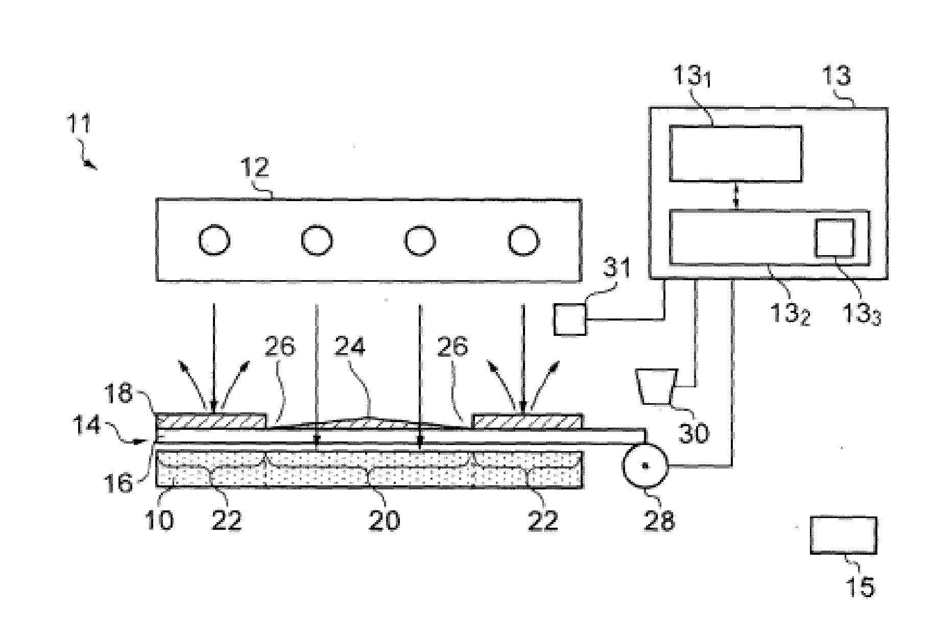
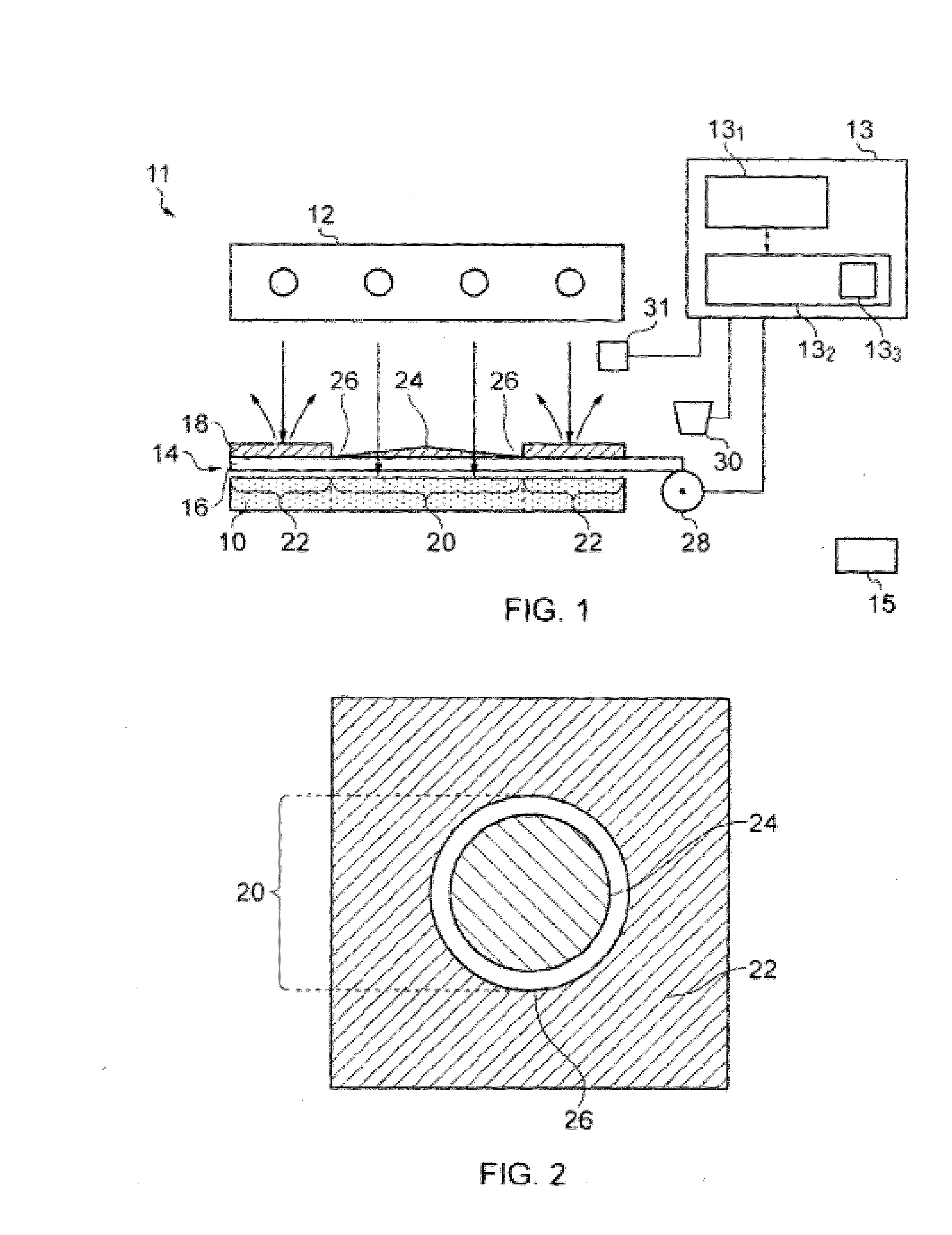
[0106]FIG. 1 illustrates apparatus for sintering particulate material in which an obscurer 14 (i.e. a mask) is provided for selectively obscuring the radiation provided by the source 12 on the surface portion of the layer 10 to thereby vary the intensity of the radiation incident on the surface portion of the layer 10. The obscurer 14 comprises a radiation transmissive substrate 16, such as a glass plate, which carries a varying amount of radiation reflective material 18, such as aluminium oxide. The amount and pattern of material 18 deposited on the substrate may be varied to selectively vary the intensity of radiation incident on the surface portion of the layer 10, as will be described hereinafter.

[0107]Referring also to FIG. 2, the surface portion of the layer 10 is logically divided by the obscurer 14 into a number of areas including a combination portion 20, which is to be exposed to radiation to combine the particulate material, and a non-combination portion 22 which is to be...

second embodiment

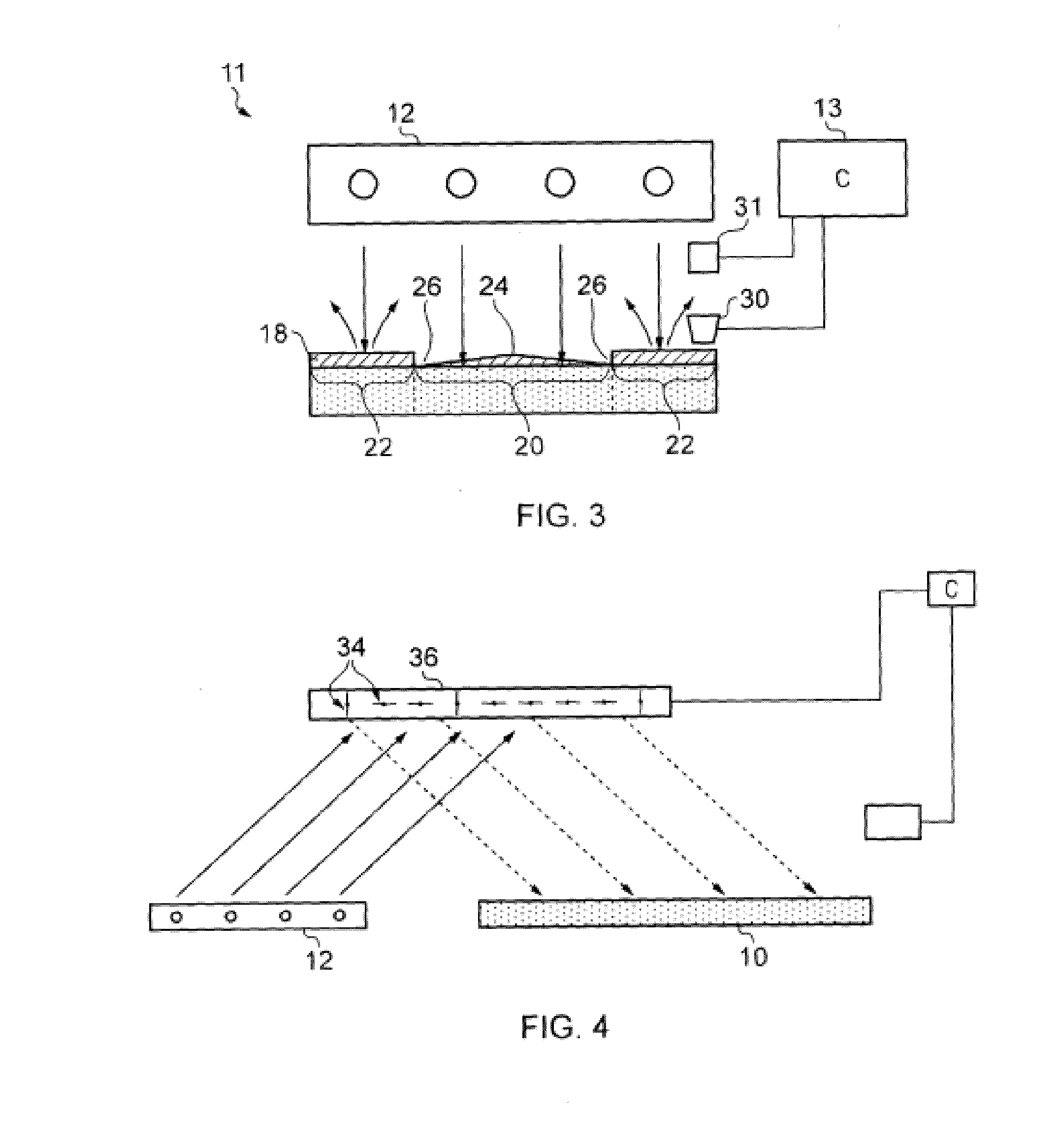
[0115]FIG. 3 illustrates apparatus for combining particulate material, in which corresponding elements are given corresponding reference numerals. The apparatus of FIG. 3 is similar to that shown in FIG. 1, except that instead of the reflective material 18 being deposited onto a substrate 16, the reflective material 18 is deposited, using the printing head 30, directly onto the surface portion of the layer 10 of particulate material.

[0116]In the apparatus of this embodiment, the printing head 30 is again controlled by the controller 13 which controls both the movement of the head 30 across the surface of the layer 10 and the rate of deposition of reflective material 18 onto the layer 10. Again, real time measurement of the surface temperature of the layer 10 may be carried out using a temperature measurement device 31, for example, a pyrometer P or thermal imaging camera, the temperature measurement being used by the controller 13 to determine the amount of reflective material 18 to...

fourth embodiment

[0120]FIG. 5 illustrates apparatus for combining particulate material which is similar to the embodiments described above and in which corresponding elements have been given corresponding reference numerals.

[0121]The apparatus of FIG. 5 is most similar to the apparatus of FIG. 3 in that material is deposited directly onto the surface portion of the layer 10 of particulate material. However, according to the fourth embodiment, the material is a radiation absorbent material 50, for example a material including carbon black in powder form. In use, radiation provided by the radiation source 12 is absorbed by the radiation absorbent material 50 where it is present on the surface, causing the radiation absorbent material 50 to heat up. Heat from the radiation absorbent material 50 is transferred to the underlying particulate material raising the temperature of individual particles of the particulate material. As the particles are heated to a temperature approaching their melting temperatu...


PUM

PropertyMeasurementUnit
distanceaaaaaaaaaa
heightaaaaaaaaaa
temperatureaaaaaaaaaa

Abstract

A method of selectively combining particulate material, comprising: (i) providing a layer of particulate material to a part bed; (ii) providing radiation to sinter a portion of the material of the layer; (iii) providing a further layer of particulate material overlying the prior layer of particulate material including the previously sintered portion of material; (iv) providing radiation to sinter a further portion of the material within the overlying further layer and to sinter said further portion with the previously sintered portion of material in the prior layer; (v) successively repeating blocks (iii) and (iv) to form a three-dimensional object; and wherein at least some of the layers of particulate material are pre-heated with a heater prior to sintering a portion of the material of the respective layer, the heater being configured to move relative to, and proximate, the particulate material.

Description

TECHNOLOGICAL FIELD[0001]Embodiments of the present invention relate to methods and apparatus for selectively combining particulate material.BACKGROUND[0002]Rapid Prototyping is widely used to form prototype components, and a number of apparatus and methods are currently available for carrying out rapid prototyping. In one method, a computer generated three dimensional model of the component is initially produced using computer assisted drawing (CAD) software. The three dimensional model is then sliced into a number of virtual layers, and a device is then used to form the layers from particulate material and sinter the layers to create the three dimensional object.[0003]When forming a three dimensional object, the particulate material usually needs to be relatively cool in order to flow smoothly and be reliably and evenly deposited onto the build surface. If the particulate material is too hot when being deposited, it will flow poorly and can cause build failure or poor part quality...

Claims


Application Information

Patent Timeline
Patent Type & Authority Applications(United States)
IPC IPC(8): B22F3/00B29C67/00
CPCB22F3/008B22F3/003B29C67/0088B29C67/0077B29C2035/0838B29C64/153B33Y10/00B33Y30/00B33Y50/02B33Y40/00B29C64/393B29C64/295Y02P10/25B22F10/28B22F12/13B22F10/362B22F12/90B22F12/38B22F12/55B22F3/1017B22F10/00B29C67/00B22F3/105B29C35/08
Inventor HOPKINSON, NEILTHOMAS, HELEN RHIANNON
Owner LOUGHBOROUGH UNIV
Why Eureka
Try Eureka