Active bed mount for surgical robot

a surgical robot and active technology, applied in the field of robotic surgery, can solve the problems of loss of the positional relationship between the robot and the bone, loss of the defined spatial relationship between the robot coordinate system and the bone, and the robot position is no longer defined, so as to reduce the amount of applied force, reduce the risk of injury, and reduce the effect of surgical pain

Active Publication Date: 2014-10-23
MAZOR ROBOTICS
View PDF0 Cites 133 Cited by
  • Summary
  • Abstract
  • Description
  • Claims
  • Application Information

AI Technical Summary

Benefits of technology

[0010]In order to enable the tool guide to continue to move freely with movement of the patient, as previously mentioned, the mounting member is attached to the base element through a dual purpose, controlled coupling joint which both enables the mounting member to freely follow the patient bone motion, and in addition, can lock into a controlled mode in order to resist excessive applied force. This joint can be based on one or more of swiveling, spherical or translational joints, or a combination thereof, such that although the base element itself is static, the mounting member can move freely relative to the base element with motion of the bone of the patient, such as rising and falling with the breathing motion of the patient. So long as excessive forces are not applied by the surgical tool onto the bone of the patient, this is the status of the system, with the tool guide and its mounting member moving freely in unison with movement of the patient.
[0011]In order to ensure that excessive forces are not applied to the K-wire or any other clamping device used to correlate the position of the tool guide to the bone structure of the subject, the system also incorporates an active feedback mechanism. One or more controlled motor drives are incorporated into the base element or the mounting member, to control the position or force/moment of the controlled joint or joints attaching the mounting member to the static base element. So long as the force being applied by the surgical tool is less than the predetermined threshold, the control motor drives are declutched or disconnected or free-running by use of a back drivable servo system, and allow the mounting member with the tool guide to move freely and uncontrolled with motion of the patient.
[0012]Once an excessive force is detected, these motor drives apply a reactive force to the mounting member to counteract force above the predetermined threshold level exerted by a surgical tool held in the tool guide, onto the bone being operated on. The control input to this motor drive may be obtained by a force sensor incorporated in the clamping path used to attach the tool guide to the bone structure of the subject, most conveniently in the rigid mechanical attachment eleme

Problems solved by technology

However, in either of the systems described in the above referenced prior art, if the robot is attached rigidly to the patient's bone, either directly to the bone, or on a structure such as a bridge attached rigidly to the bone, and significant force is exerted by the surgeon onto a surgical tool, such as a surgical drill, there is a danger that the force of the tool on the bone, or the components of side forces on the drill guide transferred to the bone-mounting element, may be sufficient in some cases, to detach the attachment clamp from the bone, such that the robot position is no longer defined relative to the bone.
Even if complete detachment does not occur, the exerted force may be sufficient to overcome the clamping friction of the clamp with the bone, and thus to shift the position of the clamp on the bone, with the same end result of loss of positional relationship between the robot and the bone.
Furthermore, even if no movement of the clamp from the bone occurs, such excessive force may res

Method used


Image

  • Active bed mount for surgical robot
  • Active bed mount for surgical robot
  • Active bed mount for surgical robot

Examples


Embodiment Construction

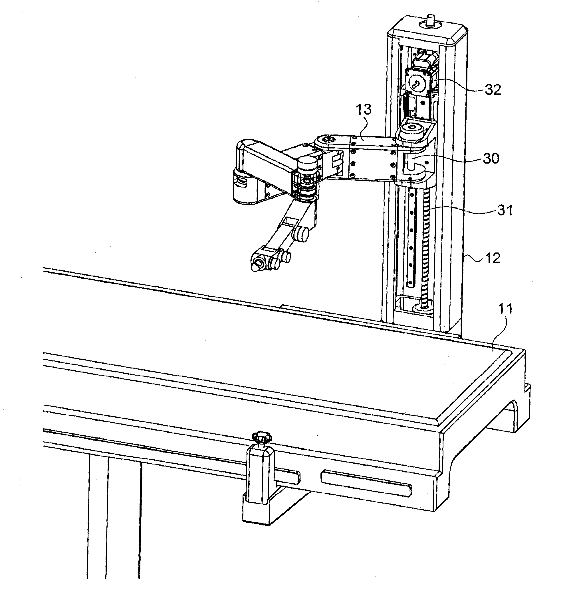
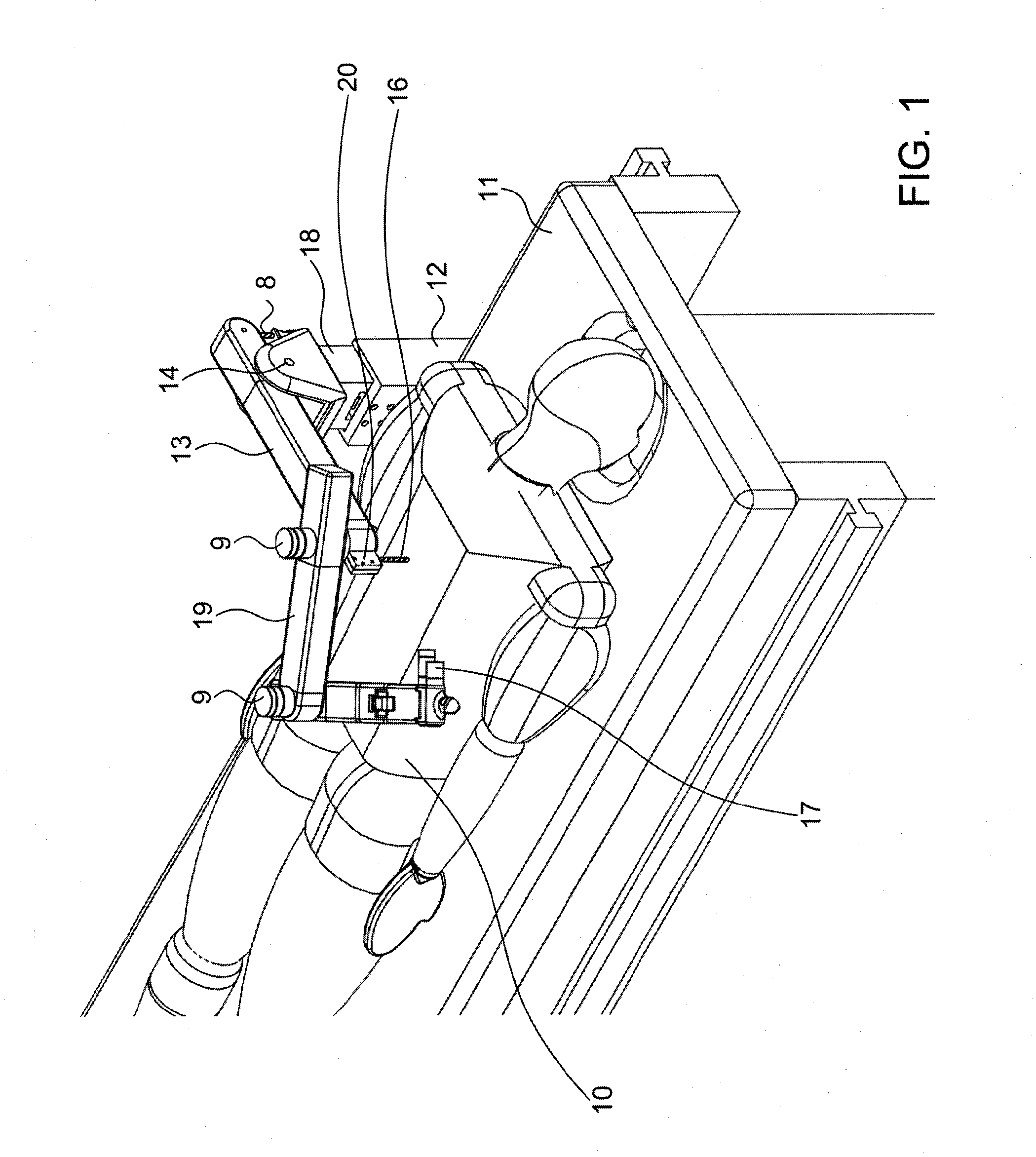
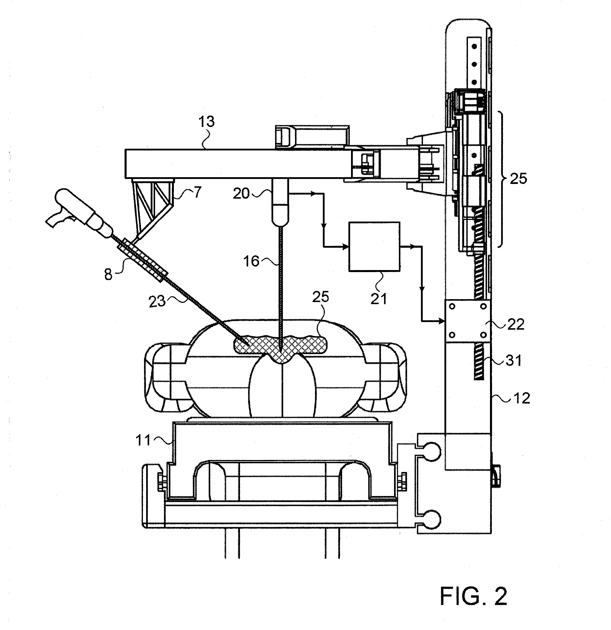
[0065]Reference is now made to FIG. 1, which illustrates schematically a first exemplary system for performing robotically guided operations on a subject, using an active bed-mounted system, as described in the present application. In the example of FIG. 1, and of the other drawings in this disclosure, the system is shown performing orthopedic surgery on the patient's spine, though it is to be understood that this is only one possible use of such a system, and it is not intended to limit the application in any way. The robot shown in this exemplary system comprises a linked series of articulated arms 19, coupled together by means of controlled angular motion links 9, such that the complete arm system generates the robotically controlled motion. A surgical robotic actuator 17 or a simple tool guide is shown at the extremity of the controlled articulated arms 19. The robotic arm system 19 is supported on a mechanical mounting member 13. Such an articulated arm robotic system 19 is onl...


PUM


Abstract

A robotic surgical system incorporating a surgical robot attached to a patient's bone by an attachment member, such that motion of the bone induces corresponding motion of the robot, maintaining the robot/bone positional relationship. The robot is supported on a mechanical mounting member attached through a controlled joint to a bed-mounted base element. The controlled joint can alternatively enable the mechanical mounting member to move freely relative to the base element, or its position can be controlled by signal inputs adapted to prevent excessive force being applied in the system. Two modes of operation are available (i) free motion in which the control system is decoupled from the mounting member, which rides freely with patient bone motion, and (ii) servo-controlled motion, in which drive mechanisms control the joint motion to prevent application of excessive force on the patient bone or attachment member.

Description

FIELD OF THE INVENTION[0001]The present invention relates to the field of robotic surgery, especially for spinal surgery performed by a bone attached tool guide or miniature surgical robot.BACKGROUND OF THE INVENTION[0002]In U.S. Pat. No. 6,837,892, for “Miniature Bone-attached Surgical Robot” to one of the inventors of the present application, for there is described a miniature surgical robot attached directly to a bone of a patient, the robot's position being registered relative to preoperative images taken of the operation site. Because of the rigid attachment of the robot to the patient's bone structure, the position of the robot is fixed relative to the bone or bones to be operated on, such that motion of the patient during the operation, whether from the breathing of the patient, or whether from actual movement of the patient's body position, does not affect the position of the operating tool held by the robot relative to the bone or bones to be operated on.[0003]In U.S. Pat. ...

Claims


Application Information

Patent Timeline
IPC IPC(8): A61B19/00
CPCA61B19/2203Y10S901/09A61B2019/2207A61B17/1757A61B2017/00694A61B34/32A61B2090/064A61B90/50A61B2090/571A61B34/30A61B90/11
Inventor BAR, YOSSEFZEHAVI, ELISHOHAM, MOSHEGROBERMAN, DAVID
Owner MAZOR ROBOTICS
Why Eureka
Try Eureka