Systems and Methods for Energy-Efficient Control of an Energy-Consuming System

a technology of energy-consuming systems and energy-efficient control, applied in the direction of instruments, heating types, static/dynamic balance measurement, etc., can solve the problems of substantial latency, blockage of hvac operation, immediate, delayed or long-term consequence, etc., and achieve the effect of less energy-efficient and efficient control of energy-consuming systems

Active Publication Date: 2014-10-23
GOOGLE LLC
View PDF33 Cites 188 Cited by
  • Summary
  • Abstract
  • Description
  • Claims
  • Application Information

AI Technical Summary

Benefits of technology

[0017]Embodiments of this disclosure relate to systems and methods for efficiently controlling energy-consuming systems, such as a heating, ventilation, or air conditioning (HVAC) system. For example, a method may involve—via one or more electronic devices configured to effect control over such a system—encouraging a user to select a first, more energy-efficient, temperature setpoint over a second, less energy-efficient, temperature setpoint and, perhaps as a result, receiving a user selection of the first temperature setpoint. Thus, using this more efficient temperature setpoint, a schedule of temperature setpoints used to control the system may be generated or modified.

Problems solved by technology

However, some wiring errors are serious enough such that HVAC operation is blocked.
The new setting can cause an immediate, delayed or long-term consequence.
For cases in which the local device “owns” the feedback display decision, one issue arises for cases in which a remote device, such as a smartphone, is being used to remotely adjust the relevant setting on the local device, because there may be a substantial latency between the time the local device has triggered the feedback display decision and the time that a corresponding feedback display would actually be shown to the remote user on the remote device.
Thus, in the case of a thermostat, it could potentially happen that the remote user has already turned the setpoint temperature to a very responsible level, but because the feedback did not show up immediately, the user is frustrated and may feel the need to continue to change the setpoint temperature well beyond the required threshold.

Method used


Image

  • Systems and Methods for Energy-Efficient Control of an Energy-Consuming System
  • Systems and Methods for Energy-Efficient Control of an Energy-Consuming System
  • Systems and Methods for Energy-Efficient Control of an Energy-Consuming System

Examples


example 1

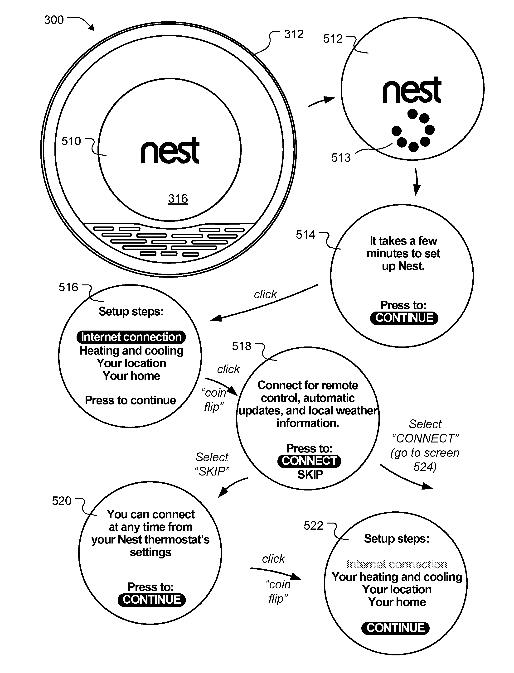
[0269]A thermostat is provided. Thermostat settings can be explicitly adjusted by a user or automatically learned (e.g., based on patterns of explicit adjustments, motion sensing or light detection). The thermostat wirelessly communicates with a central server, and the central server supports a real-time interface. A user can access the interface via a website or app (e.g., a smart-phone app). Through the interface, the user can view device information and / or adjust settings. The user can also view device information and / or adjust settings using the device itself.

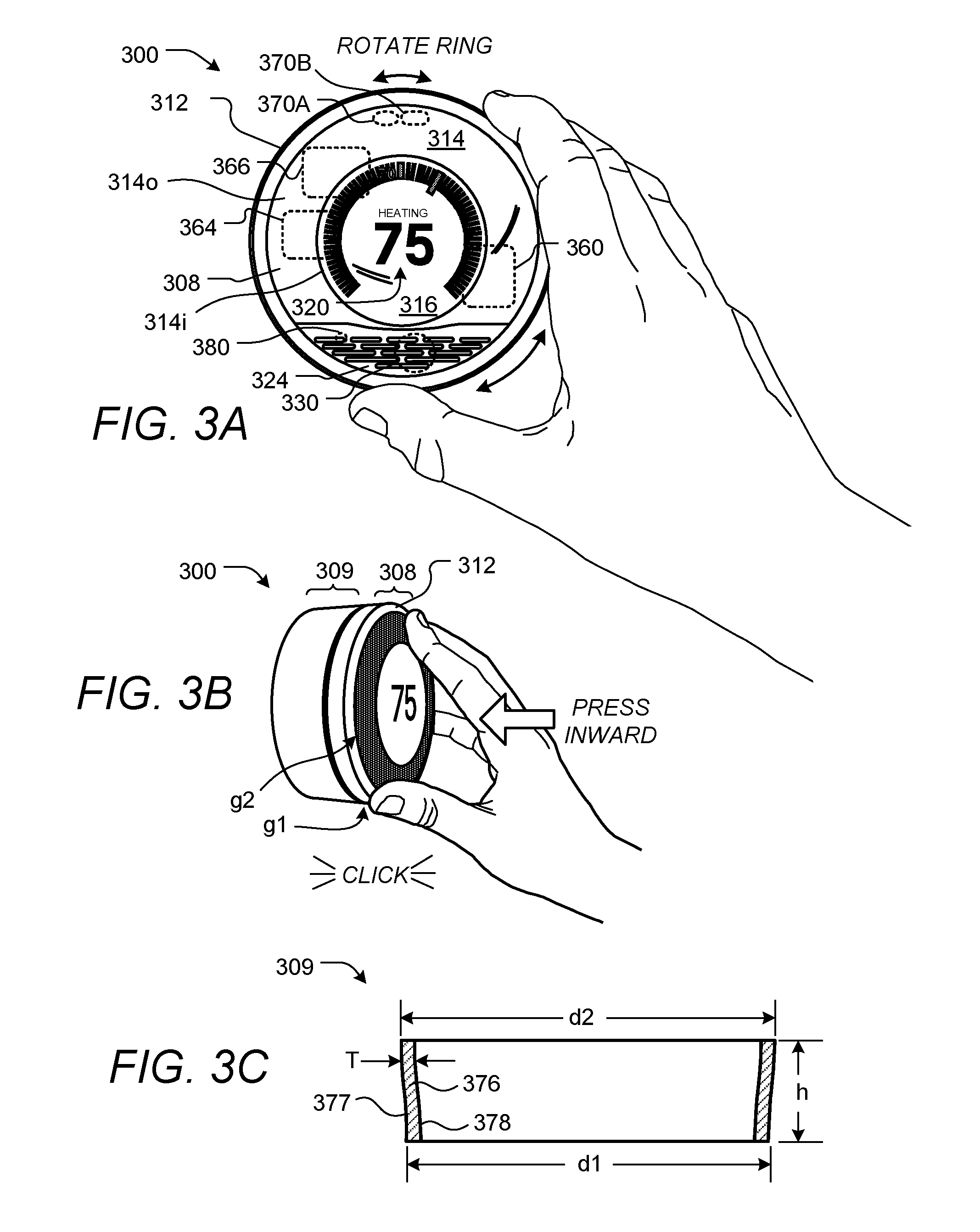
[0270]A feedback criterion indicates that a leaf icon is to be displayed to the user when the user adjusts a heating temperature to be two or more degrees cooler than a current scheduled setpoint temperature. A current scheduled setpoint temperature is 75 degrees F. Using a rotatable ring on the thermostat, a user adjusts the setpoint temperature to be 74 degrees F. No feedback is provided. The device nevertheless transmits...

example 2

[0272]A computer is provided. A user can control the computer's power state (e.g., on, off, hibernating, or sleeping), monitor brightness and whether accessories are connected to and drawing power from the computer. The computer monitors usage in five-minute intervals, such that the computer is “active” if it receives any user input or performs any substantive processing during the interval and “inactive” otherwise.

[0273]An efficiency variable is generated based on the power used by the computer during inactive periods. The variable scales from 0 to 1, with 1 being most energy conserving. A feedback criterion indicates that a positive reinforcement or reward icon is to be displayed each morning to the user when the variable is either about 0.9 or has improved by 10% relative to a past weekly average of the variable.

[0274]On Monday, a user is conscientious enough to turn off the computer when it is not in use. Thus, the variable exceeds 0.9 and a positive message is displayed to the ...

example 3

[0275]A vehicle component is provided that monitors acceleration patterns. A feedback criterion indicates that a harsh tone is to be provided if a user's cumulative absolute acceleration exceeds a threshold value during a two-minute interval. Two-minute intervals are evaluated every 15 seconds, such that the intervals overlap between evaluations. The criterion further indicates that a loudness of the tone is to increase as a function of how far the cumulative sum exceeds the threshold value.

[0276]The user encounters highway traffic and rapidly varies the vehicle's speed between 25 miles per hour and 70 miles per hour. He grows increasingly frustrated and drives increasingly recklessly. The tone is presented and becomes louder as he drives.

[0277]Specific details are given in the above description to provide a thorough understanding of the embodiments. However, it is understood that the embodiments may be practiced without these specific details. For example, circuits may be shown in ...


PUM


Abstract

Systems and methods are provided for efficiently controlling energy-consuming systems, such as heating, ventilation, or air conditioning (HVAC) systems. For example, an electronic device used to control an HVAC system may encourage a user to select energy-efficient temperature setpoints. Based on the selected temperature setpoints, the electronic device may generate or modify a schedule of temperature setpoints to control the HVAC system.

Description

CROSS-REFERENCE TO RELATED APPLICATIONS[0001]This is a continuation-in-part of U.S. Ser. No. 13 / 269,501, filed Oct. 7, 2011, which is a continuation-in-part of U.S. Ser. No. 13 / 033,573, filed Feb. 23, 2011. Both U.S. Ser. Nos. 13 / 269,501 and 13 / 033,573 claim the benefit of U.S. Prov. Ser. No. 61 / 415,771, filed Nov. 19, 2010, and U.S. Prov. Ser. No. 61 / 429,093, filed Dec. 31, 2010.[0002]This is also a continuation-in-part of U.S. Ser. No. 13 / 632,118, filed Sep. 30, 2012, which is a continuation-in-part of U.S. Ser. No. 13 / 434,560, filed Mar. 29, 2012. U.S. Ser. No. 13 / 434,560 is a continuation-in-part of U.S. Ser. No. 13 / 269,501, filed Oct. 7, 2011; is a continuation-in-part of U.S. Ser. No. 13 / 317,423, filed Oct. 17, 2011; is a continuation-in-part of PCT Ser. No. PCT / US11 / 61437, filed Nov. 18, 2011; is a continuation-in-part of PCT Ser. No. PCT / US12 / 30084, filed Mar. 22, 2012; and claims the benefit of U.S. Prov. Ser. No. 61 / 627,996, filed Oct. 21, 2011. As noted above, U.S. Ser. N...

Claims


Application Information

Patent Timeline
Patent Type & Authority Applications(United States)
IPC IPC(8): F24F11/00
CPCF24F11/0009F24F2221/32G05D23/1904F24F11/30F24F11/46F24F11/52F24F11/64F24F11/523G05B15/02G08B29/02
Inventor FADELL, ANTHONY MICHAELMATSUOKA, YOKYSLOO, DAVIDPLITKINS, MICHAELMATAS, MICHAEL JAMESROGERS, MATTHEW LEEFISHER, EVAN J.LEE, ERIC A.HALES, IV, STEVEN A.STEFANSKI, MARK D.SHARAN, RANGOLI
Owner GOOGLE LLC
Why Eureka
Try Eureka