Vehicle control device and vehicle control method

a control device and vehicle technology, applied in the direction of brake systems, cycle equipment, instruments, etc., can solve the problem of difficult to obtain the desired vehicle body orientation using only driving force from a motive power sour

Active Publication Date: 2014-10-23
NISSAN MOTOR CO LTD
View PDF17 Cites 21 Cited by
  • Summary
  • Abstract
  • Description
  • Claims
  • Application Information

AI Technical Summary

Benefits of technology

[0007]An object of the present invention is to provide a vehicle control device ...

Problems solved by technology

However, the problem exists that it is difficult to obtain a desired v...

Method used


Image

  • Vehicle control device and vehicle control method
  • Vehicle control device and vehicle control method
  • Vehicle control device and vehicle control method

Examples


first embodiment

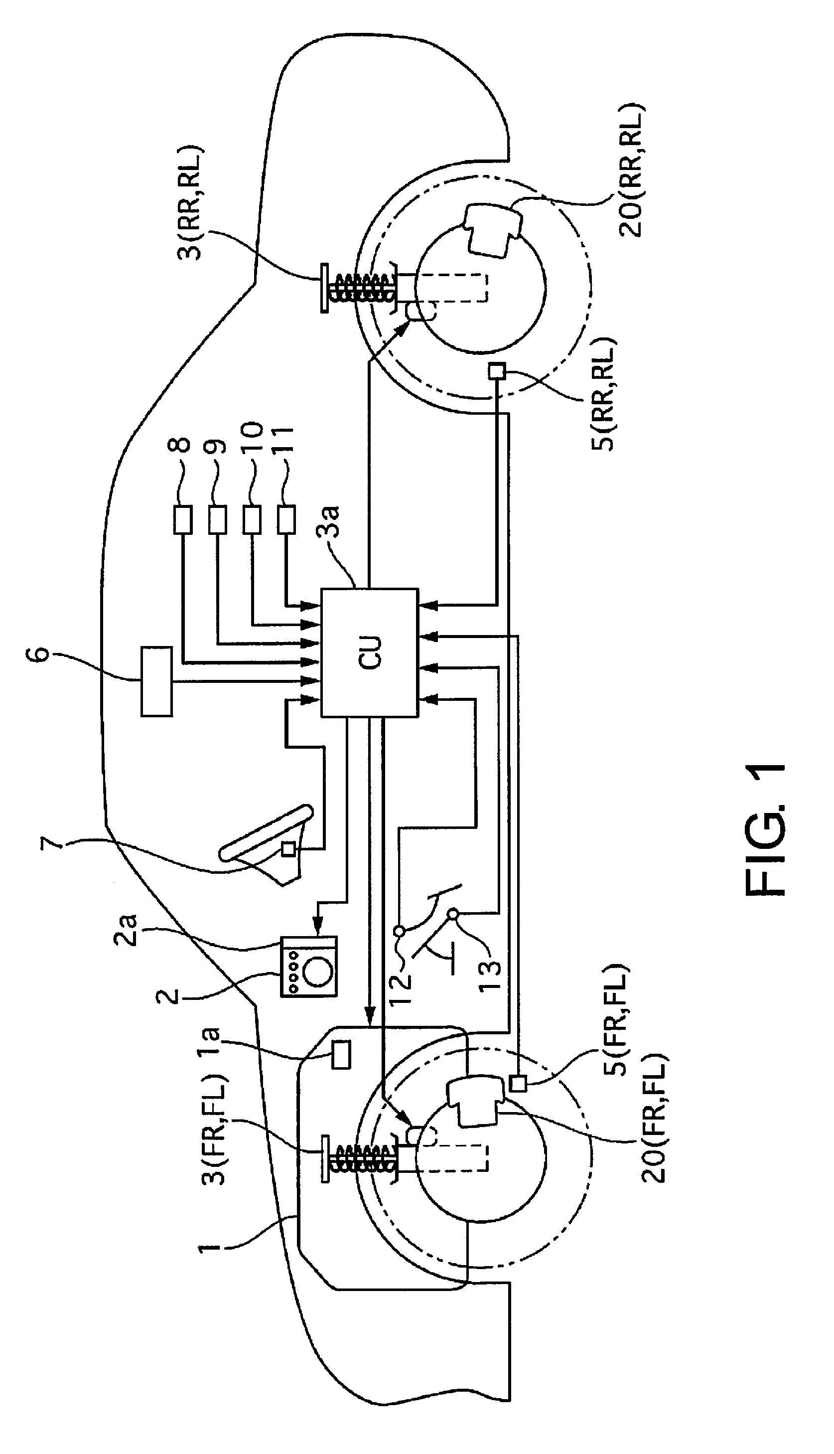
[0037]FIG. 1 is a schematic system diagram of a vehicle control device according to a first embodiment. A vehicle comprises an engine 1 constituting a power source, brakes 20 for generating braking torque by applying frictional force to the wheels (brakes corresponding to individual wheels will be referred to hereafter as follows: front right brake: 20FR; front left brake: 20FL; rear right brake: 20RR; rear left brake: 20RL), and variable-damping-force shock absorbers 3 provided between each of the wheels and the vehicle body (“shock absorber” will be abbreviated “S / A” in the following description; shock absorbers corresponding to individual wheels will be referred to as follows: front right S / A: 3FR; front left S / A: 3FL; rear right S / A: 3RR; rear left S / A: 3RL).

[0038]The engine 1 comprises an engine controller 1a (also referred to hereafter as an engine control unit) for controlling the torque outputted by the engine 1; the engine controller 1a controls the engine operation state (...

second embodiment

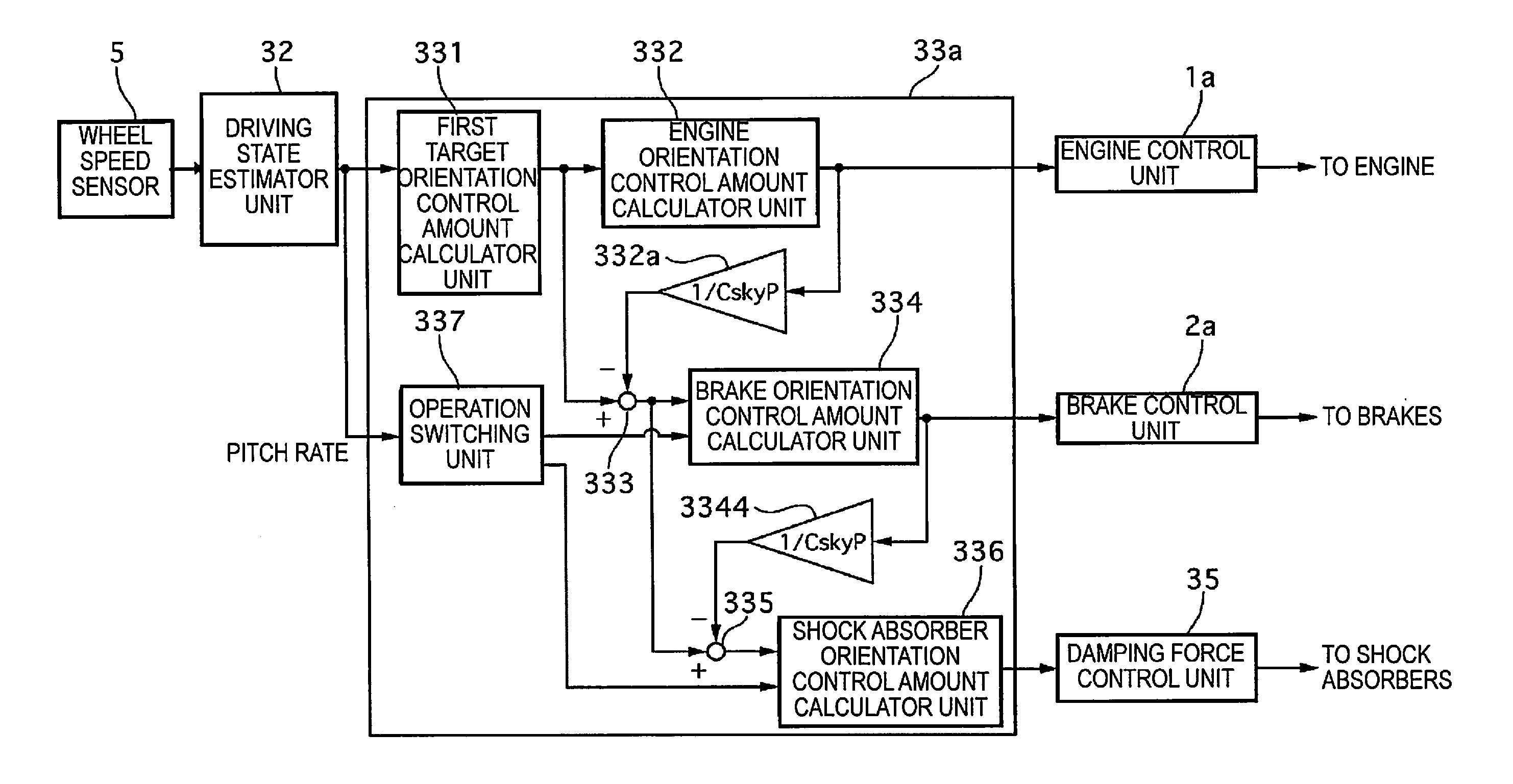
[0204]FIG. 24 is a control block diagram of actuator control amount calculation processes performed during pitch control in a second embodiment. The second embodiment differs from the first embodiment in that the operation switching unit 337 switches the operation of the actuators on and off on the basis of the roll rate instead of the pitch rate.

[0205]In the second embodiment, the action of the operation switching unit 337 causes pitch control to be performed using the engine torque control amount alone when the absolute value of the amplitude of the roll rate is less than a first predetermined value, using the damping force control amount instead of the engine torque control amount when the absolute value of the amplitude of the roll rate is equal to or greater than the first predetermined value and less than the second predetermined value, and using the braking torque control amount instead of the engine torque control amount or the damping force control amount when the absolute ...

third embodiment

[0209]FIG. 25 is a control block diagram of actuator control amount calculation processes performed during pitch control in a third embodiment. The third embodiment differs from the first embodiment in that the S / A orientation control amount calculator unit 336 performs a damping force minimization control process that sets a lower pitch orientation control amount when the stroke speed is low compared to when stroke speed is high. The damping force minimization control process will now be described. FIG. 26 is a profile graph showing the relationship of control force against stroke speed in the third embodiment. The x axis represents stroke speed, and the y axis represents control force. Control force is a value that is proportionate to damping force; increases in damping force lead to corresponding increases in control force for controlling orientation, and decreases in damping force lead to corresponding decreases in control force for controlling orientation.

[0210]Here, the S / As 3...


PUM


Abstract

A vehicle control device includes a motive power source orientation control device, a friction brake orientation control device, a damping force control device, and an orientation control device. The orientation control device controls vehicle body orientation via the motive power source orientation control device when the absolute value of the amplitude of a detected state quantity is less than a first predetermined value, via the damping force control device in addition to the motive power source orientation control device when the absolute value of the amplitude is equal to or greater than the first predetermined value and less than a second predetermined value greater than the first predetermined value, and via the friction brake orientation control device in addition to the motive power source orientation control device and the damping force control device when the absolute value of the amplitude is equal to or greater than the second predetermined value.

Description

CROSS-REFERENCE TO RELATED APPLICATIONS[0001]This application is a U.S. National stage application of International Application No. PCT / JP2013 / 051173, filed Jan. 22, 2013, which claims priority to Japanese Patent Application No. 2012-012599 filed in Japan on Jan. 25, 2012, Japanese Patent Application No. 2012-012600 filed in Japan on Jan. 25, 2012, Japanese Patent Application No. 2012-012601 filed in Japan on Jan. 25, 2012, Japanese Patent Application No. 2012-100588 filed in Japan on Apr. 26, 2012 and Japanese Patent Application No. 2012-100590 filed in Japan on Apr. 26, 2012, the contents of each of which are hereby incorporated herein by reference.BACKGROUND[0002]1. Field of the Invention[0003]The present invention relates to a control device and a control method for controlling the state of a vehicle.[0004]2. Background Information[0005]Japanese Laid-Open Patent Application No. 2009-247157 discloses a technique of controlling vehicle body orientation using drive force from a mot...

Claims


Application Information

Patent Timeline
IPC IPC(8): B60G17/0165
CPCB60G17/0165B60G17/0195B60G17/06B60G2400/821B60G2400/91B60G2500/10B60T7/12B60T8/17555B60T13/662B60T2260/06B60W10/06B60W10/184B60W10/22B60W30/20B60W2030/206B60W2520/16B60W2710/0666B60W2710/182B60W2710/223B60W2710/226
Inventor KIKUCHI, HIRONOBUHIRAYAMA, KATSUHIKO
Owner NISSAN MOTOR CO LTD
Why Eureka
Try Eureka